Isuzu N-Series. Manual - part 516


  Index      Isuzu     Isuzu N-Series - service repair manual


Search            


Content   ..  514  515  516  517   ..


Isuzu N-Series. Manual - part 516


Engine Mechanical (4HK1-TC)   6A-169

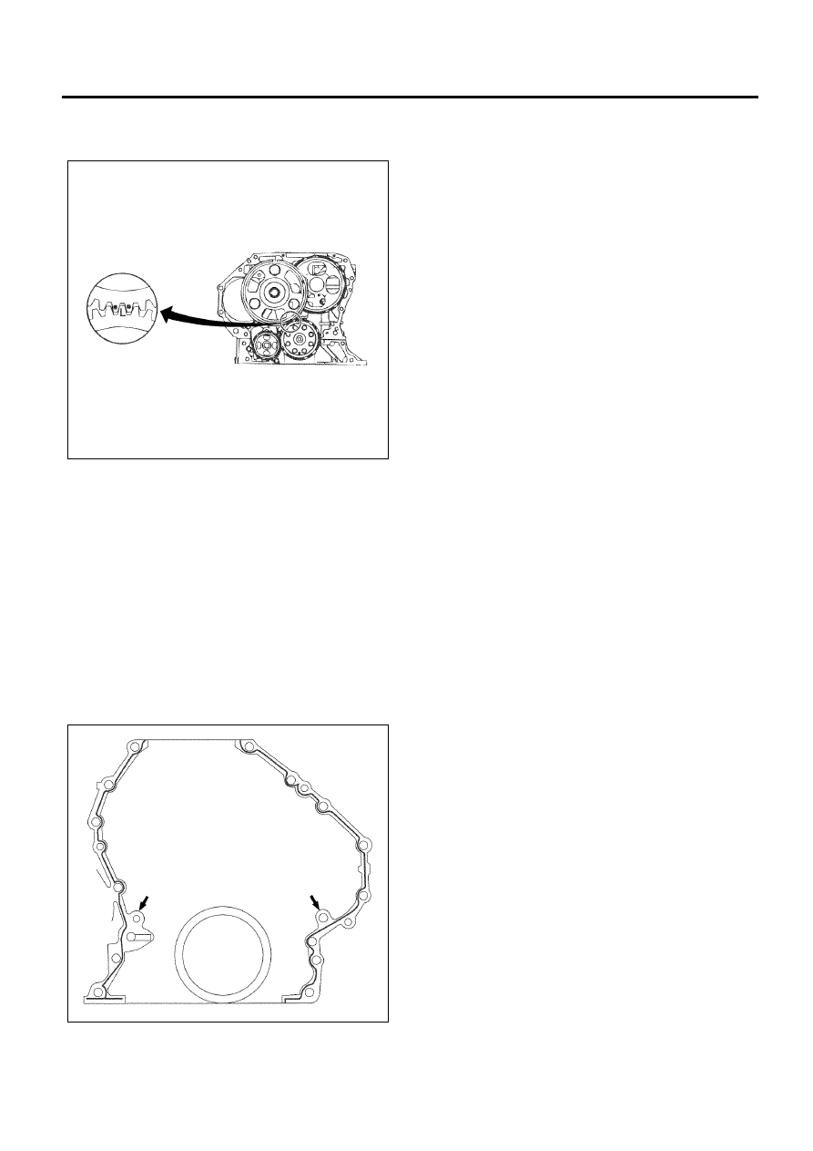
• Match the coincidence marks of the crankshaft

gear and the idle gear A, and install them on
the cylinder block. 

• Tighten the mounting bolts using the specified

torque.

Tighten:
Bolts to 133 N

⋅m (13.6 kg⋅m/98 lb⋅ft)

3. Install the flywheel housing.

• Clean properly the rear surface of the cylinder

block. Remove the protruding fluid gasket
thoroughly, especially, when mounting the
crankcase.

• Apply the liquid gasket (ThreeBond1207C)

uniformly on the inside surface of the bolt holes
(excluding the bolt holes indicated by arrows)
as shown in the figure.

• After applying the liquid gasket, quickly install it.

• Match the dowel pin of the cylinder block and

then install the flywheel housing. 

Tighten:
Bolts (1) to 96 N

⋅m (9.8 kg⋅m/71 lb⋅ft)

Bolts (2) to 77 N

⋅m (7.9 kg⋅m/57 lb⋅ft)

Bolts (3) to 38 N

⋅m (3.9 kg⋅m/28 lb⋅ft)

• The seal is tightened from the cylinder block

side.

N6A6322E

N6A6069E

6A-170   Engine Mechanical (4HK1-TC)

4. Install the power steering pump idling gear.

• Apply the engine oil on the gear assembly unit

of the idling gear shaft.

• Assemble the idling gear and the shaft in the

direction shown in the figure, mount it on the
flywheel housing, and tighten it using the
specified torque. 

Tighten:
Bolt to 133 N

⋅m (13.6 kg⋅m/98 lb⋅ft)

5. Install the idling gear cover of the power steering

pump. 

• Install the O-ring on the cover and on the

flywheel housing, and tighten the fixing bolts
using the specified torque.

Tighten:
Bolt to 19 N

⋅m (1.9 kg⋅m/14 lb⋅ft)

N6A6070E

N6A6072E

N6A6071E

Engine Mechanical (4HK1-TC)   6A-171

6. Install the power steering pump and tighten it using

the specified torque.

Tighten:
Flywheel housing fixing bolt (1) to 43 N

⋅m (4.4 kg⋅m/32

lb

⋅ft)

Cylinder block fixing bolts (2) to 44 N

⋅m (4.5 kg⋅m/33

lb

⋅ft)

Without HBB

With HBB

Legend

1. Flywheel Housing Bolt
2. Cylinder Block Bolt


7. Install the oil pan.

Refer to “Oil Pan”.

8. Install the rear seal of the crankshaft.

Refer to “Crankshaft Rear Oil Seal”.

9. Install the flywheel.

Refer to “Flywheel”.

10. Install the fuel supply pump assembly.

Refer to “Fuel Supply Pump” in Section 6C.

11. Install the clutch plate assembly. 

12. Install the clutch pressure plate assembly.

• Insert the clutch aligner in the spline of the

clutch plate assembly.

• Install the clutch plate assembly on the

flywheel. 

N6A6073E

N6A0775E

N6A6074E

6A-172   Engine Mechanical (4HK1-TC)

• Match the mounting hole of the clutch pressure

plate assembly with the dowel pin of the
flywheel, and install the clutch pressure plate
assembly on the flywheel. 

Legend

1. Clutch Aligner


• Tighten the clutch pressure plate assembly in

the sequence shown in the figure using the
specified torque.

Tighten:
Bolts to 40 N

⋅m (4.1 kg⋅m/30 lb⋅ft)

13. Install the cylinder head assembly.

Refer to “Cylinder Head”.

14. Install the camshaft assembly.

Refer to “Camshaft Assembly”.

15. Install the rocker arm shaft assembly.

Refer to “Rocker Arm Shaft Assembly”. 

16. Tighten the cylinder head cover.

Refer to “Cylinder Head Cover”.

N6A6218E

N6A6217E


Content   ..  514  515  516  517   ..