Isuzu N-Series. Manual - part 517


  Index      Isuzu     Isuzu N-Series - service repair manual


Search            


Content   ..  515  516  517  518   ..


Isuzu N-Series. Manual - part 517


Engine Mechanical (4HK1-TC)   6A-173
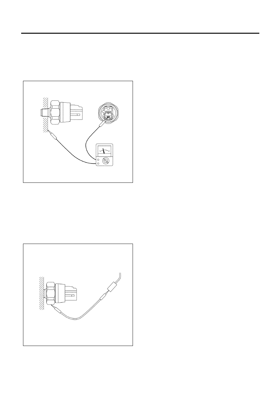
Oil Pressure Switch

Inspection

Check the continuity between the switch terminal and
the body grounding in the no-load condition.
If there is no connectivity, replace with normal parts.
(Refer to “Oil Filter Assembly”)

Circuit check

1. Turn the starter switch to ON.
2. Disconnect the oil pressure switch connector, and

confirm that the oil pressure-warning lamp lights
when the connector on the harness side is
grounded.
If the warning lamp does not light up, check the
circuit between the meter and the oil pressure
switch, and repair the disconnected locations.

N6A6323E

N6A6324E

6A-174   Engine Mechanical (4HK1-TC)

Air Cleaner Element

Removal

1. Remove the air cleaner cover fixing bolt.
2. Remove the air cleaner element assembly.

Inspection

• Check for damage to the element or clogging due

to dirt. If the element is damaged, then replace it. If
clogged, then clean it.

• The viscous-type (wet type) element cannot be

cleaned; therefore, it has to be replaced if it is very
dirty.

Installation

1. Install the air cleaner element assembly.
2. Tighten the air cleaner cover fixing bolt.

Cleaning

Dry type element

• While rotating the element, blow air under 690 kPa

(7.0 kg/cm

2

 / 100 psi) and remove the dust.

• Dissolve the filter cleaner ND1500 in water and

soak the element for approximately 30 minutes.
Then wash it properly with water and allow it to dry
in natural conditions (two to three days.)

Replacement period

Every  40,000 km  (24,000
miles) or every two years

N6A6325E

Cooling System   6B-1

ENGINE

Cooling System

TABLE OF CONTENTS

Cooling System . . . . . . . . . . . . . . . . . . . . . . . . . . . 6B-2

Service Precautions . . . . . . . . . . . . . . . . . . . . . . 6B-2
Functional Check . . . . . . . . . . . . . . . . . . . . . . . . 6B-5
A List of Defective Phenomena . . . . . . . . . . . . . 6B-7
Main Data and Specifications. . . . . . . . . . . . . . . 6B-7

Water Pump  . . . . . . . . . . . . . . . . . . . . . . . . . . . . . 6B-9

Components. . . . . . . . . . . . . . . . . . . . . . . . . . . . 6B-9
Removal . . . . . . . . . . . . . . . . . . . . . . . . . . . . . . 6B-10
Inspection. . . . . . . . . . . . . . . . . . . . . . . . . . . . . 6B-11
Installation  . . . . . . . . . . . . . . . . . . . . . . . . . . . . 6B-11
Torque Specifications . . . . . . . . . . . . . . . . . . . . 6B-13

Thermostat  . . . . . . . . . . . . . . . . . . . . . . . . . . . . . 6B-14

Components. . . . . . . . . . . . . . . . . . . . . . . . . . . 6B-14
Removal . . . . . . . . . . . . . . . . . . . . . . . . . . . . . . 6B-14
Inspection. . . . . . . . . . . . . . . . . . . . . . . . . . . . . 6B-14
Installation  . . . . . . . . . . . . . . . . . . . . . . . . . . . . 6B-15
Torque Specifications . . . . . . . . . . . . . . . . . . . . 6B-16

Radiator and Intercooler . . . . . . . . . . . . . . . . . . . 6B-17

Components. . . . . . . . . . . . . . . . . . . . . . . . . . . 6B-17
Removal . . . . . . . . . . . . . . . . . . . . . . . . . . . . . . 6B-17
Inspection. . . . . . . . . . . . . . . . . . . . . . . . . . . . . 6B-18
Installation  . . . . . . . . . . . . . . . . . . . . . . . . . . . . 6B-19
Torque Specifications . . . . . . . . . . . . . . . . . . . . 6B-20

Drive Belt. . . . . . . . . . . . . . . . . . . . . . . . . . . . . . . 6B-21

Components. . . . . . . . . . . . . . . . . . . . . . . . . . . 6B-21
Inspection. . . . . . . . . . . . . . . . . . . . . . . . . . . . . 6B-21
Adjustment . . . . . . . . . . . . . . . . . . . . . . . . . . . . 6B-22
Torque Specifications . . . . . . . . . . . . . . . . . . . . 6B-23

6B-2   Cooling System

Cooling System

Service Precautions

WARNING:
Do not remove the radiator cap when the cooling water
is at high temperature. Steam or boiling water will gush
out and you may be burnt. To open the radiator cap,
cover the cap with a thick cloth when the cooling water
is cool, release the pressure by slowly turning the cap,
and then remove the cap.

Explanations on Functions and Operation
Cooling Water System
The cooling water system, which is the forced
circulation system, consists of a water pump,
thermostat, and radiator as its main components.

Legend

1. Water Jacket
2. Drain Plug
3. Oil Cooler
4. Water Pump
5. Drain Cock
6. Radiator
7. Cooling Fan
8. Radiator Cap

9. Heater Core

10. Reserve Tank

11. Air Bleeding Plug

12. Water Outlet Pipe
13. Thermostat (2 nos.)
14. Thermometer Unit
15. Bypass Route
16. EGR Cooler


N6A6326E


Content   ..  515  516  517  518   ..