Isuzu N-Series. Manual - part 515
Engine Mechanical (4HK1-TC) 6A-165
Oil Pump
Components
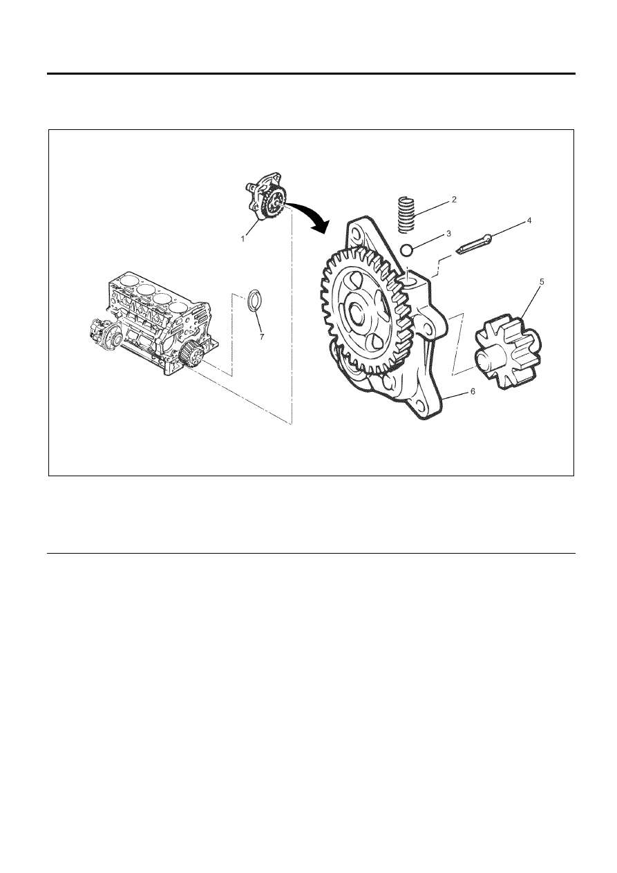
Legend
1. Oil Pump Assembly
2. Spring
3. Ball
4. Split Pin
5. Driven Gear and Shaft
6. Oil Pump Body
7. Slinger
Removal
1. Drain out the engine oil.
2. Drain out the cooling water.
3. Remove the cylinder head cover.
Refer to “Cylinder Head Cover”.
4. Remove the rocker arm shaft assembly.
Refer to “Rocker Arm Shaft Assembly”.
5. Remove the camshaft assembly.
Refer to “Camshaft Assembly”.
6. Remove the cylinder head assembly.
Refer to “Cylinder Head”.
7. Clutch pressure plate assembly
Refer to “Flywheel”.
8. Driven plate
Refer to “Flywheel”.
9. Remove the fuel supply pump assembly.
Refer to “Fuel Supply Pump” in Section 6C.
10. Remove the flywheel.
Refer to “Flywheel”.
11. Remove the rear oil seal of the crankshaft.
Refer to “Crankshaft Rear Oil Seal”.
12. Remove the oil pan.
13. Remove the power steering pump.
14. Remove the idle gear cover of the power steering
pump.
N6A6312E