Isuzu N-Series. Manual - part 369


  Index      Isuzu     Isuzu N-Series - service repair manual


Search            


Content   ..  367  368  369  370   ..


Isuzu N-Series. Manual - part 369


6A3-128 ENGINE (4HF1 / 4HF1-2 / 4HE1-TC / 4HG1 / 4HG1-T)

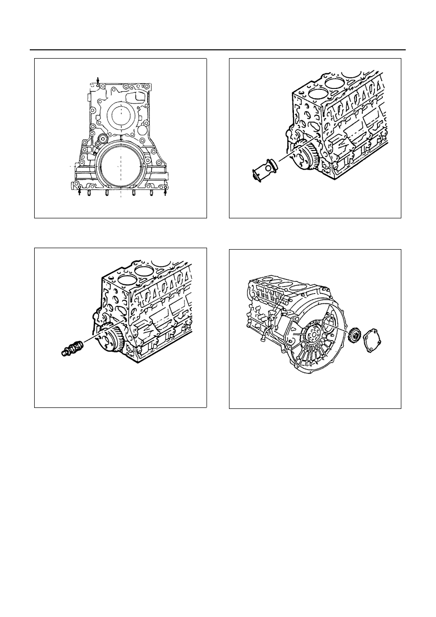
47. Oil Thermo Valve (4HF1, 4HF1-2, 4HG1, 4HG1-T)

Pull out the thermo valve from the cylinder body.

48. Bypass Valve (4HE1-TC)

Pull out the bypass valve from the cylinder body.

49. Power Steering Pump Idle Gear Cover
50. Power Steering Pump Idle Gear

51. Flywheel Housing

Notice:
Be careful not to fail to remove the bolts shown in the il-
lustration.

N6A0639E

N6A0640E

N6A0641E

N6A0431E

ENGINE (4HF1 / 4HF1-2 / 4HE1-TC / 4HG1 / 4HG1-T) 6A3-129

52. Idle Gear A

53. Idle Gear B
54. Idle Gear B Shaft

55. Oil Pump Assembly

56. Connecting Rod Cap
57. Connecting Rod Lower Bearing
58. Piston and Connecting Rod Assembly

Above works refer to “PISTON AND CONNECT-
ING ROD” section in this manual.

59. Crankcase

1) Loosen the crankcase bolts in numerical order

a little at a time.

2) Install the three crankcase fixing bolts (See ar-

row marks) to the crankcase replacer holes as
shown in the illustration, and tighten the bolts
alternate a little at a time.

Notice:
When removing the crankcase, be sure to remove the oil
pump and the generator bracket before that.

N6A0432E

N6A0562E

N6A0695E

N6A0177E

6A3-130 ENGINE (4HF1 / 4HF1-2 / 4HE1-TC / 4HG1 / 4HG1-T)

60. Thrust Bearing Lower
61. Crankshaft Bearing Lower

62. Crankshaft Assembly
63. Thrust Bearing Upper
64. Crankshaft Bearing Upper

65. Oiling Jet

Loosen the check valves to remove both the check
valves and the oiling jets.
Take care not to bend or damage the oiling jets.

66. Cylinder Block

Installation

1. Cylinder Block

Use compressed air to thoroughly clean the inside
and outside surfaces of the cylinder body, the oil
holes, and the water jackets. 

2. Oiling Jet

1) Install the oiling jets together with the check

valves.
Take care not to damage the oiling jet nozzles.

N6A0642E

N6A0643E

Legend

1. Crankshaft assembly
2. Thrust bearing upper
3. Crankshaft bearing upper

N6A0644E

N6A0700E

ENGINE (4HF1 / 4HF1-2 / 4HE1-TC / 4HG1 / 4HG1-T) 6A3-131

2) Tighten the check valves and oiling jets to the

specified torque.

Tighten:
Check valve and oiling jet to 21 N

⋅m (2.1 kg⋅m/15 lb⋅ft)

3. Crankshaft Bearing Upper

When replacing the crankshaft or the crankshaft
bearing with a new one, select the crankshaft bear-
ing according to the respective grades stamped on
the crankshaft and the cylinder body.
Refer to the “CRANKSHAFT” in section 6A.
All upper bearings have oil grooves.

1) Carefully wipe any foreign material from the up-

per bearing.

Caution:
Do not apply engine oil to the bearing back faces and
the cylinder body bearing fitting surface.

2) Locate the position mark applied at disassem-

bly if the removed upper bearings are to be re-
used.

4. Thrust Bearing Upper

Install the thrust bearing upper to the front side of
the cylinder body No.5 journal. At this time, the
thrust bearing upper may be pasted to the cylinder
body with grease. 
However, be sure to wipe off nay excessive
grease.

Caution:
The thrust bearing oil grooves must be facing the sliding
faces.

5. Crankshaft Assembly

Apply an ample coat of engine oil to the crankshaft
journals and the crankshaft bearing surfaces be-
fore installing the crankshaft with timing gear.

6. Crankshaft Bearing Lower

All lower bearings does not have oil grooves.
1) Carefully wipe any foreign material from the

lower bearing.

N6A0700E

N6A0647E

N6A0648E

N6A0649E


Content   ..  367  368  369  370   ..