Isuzu N-Series. Manual - part 370
6A3-132 ENGINE (4HF1 / 4HF1-2 / 4HE1-TC / 4HG1 / 4HG1-T)
Caution:
Do not apply engine oil to the bearing back faces and
the crankcase bearing fitting surfaces.
2) Locate the position mark applied at disassem-
bly if the removed lower bearings are to be re-
used.
7. Thrust Bearing Lower
Install the thrust bearing lower to the rear side of
the crankcase No.5 journal.
Caution:
The thrust bearing oil grooves must be facing the sliding
faces.
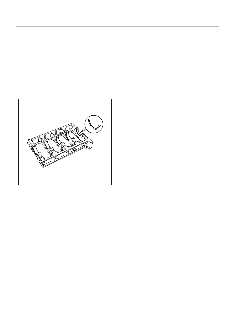
8. Crankcase
1) Apply a 3 mm (0.12 in) bead of recommended
liquid gasket (Three Bond 1207C) or its equiv-
alent to the crankcase upper surface as shown
in the illustration.
2) Carefully place the crankcase on the cylinder
body.
• Install the crankcase within 20 minutes after
application of liquid gasket.
N6A0650E