Isuzu N-Series. Manual - part 362


  Index      Isuzu     Isuzu N-Series - service repair manual


Search            


Content   ..  360  361  362  363   ..


Isuzu N-Series. Manual - part 362


6A3-100 ENGINE (4HF1 / 4HF1-2 / 4HE1-TC / 4HG1 / 4HG1-T)
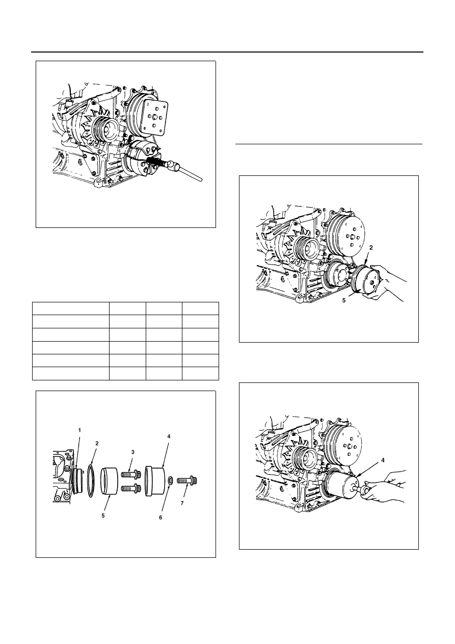
Installation

1. Crankshaft Front Slinger

Press in the slinger using the oil seal setting tool
kit.
Oil Seal Setting Tool Kit: 5-8840-2431-0
Front slinger and oil seal setting tools

1) Insert the slinger (2) into the end of adapter (5)

and install the adapter on the crankshaft.

2) Cover the sleeve (4) and tighten the bolt until

the sleeve comes to contact the adapter stop-
per (8).

Part Name

Stamp 

Slinger

Oil Seal

Adapter

FT

Sleeve

FT

Oil seal adapter ring

FT

Center bolt

Adapter bolt

N6A0600E

N6A0601E

Legend

1. Crankshaft
2. Slinger
3. Adapter bolt 
4. Sleeve
5. Adapter
6. Washer (5 mm (0.20 in))
7. Center bolt

N6A0602E

N6A0603E

ENGINE (4HF1 / 4HF1-2 / 4HE1-TC / 4HG1 / 4HG1-T) 6A3-101

3) With the slinger pressed in, make sure of mea-

surements specified in the illustration as well as
of slinger deflection.
(A): 40.5 

± 0.3 mm (1.594 ± 0.012 in)

(B): 34.0 

± 0.1 mm (1.339 ± 0.004 in)

Notice:
Be sure to replace the slinger and oil seal as a set. 
Use about 5 mm (0.20 in) thickness plain washer on the
center bolt.

2. Crankshaft Front Oil Seal

1) Apply engine oil to the lip of the oil seal.
2) Press in the oil seal using the front oil seal set-

ting tool kit.

• Remove the slinger sleeve and insert the oil

seal (4) into the adapter (3).

• Install the oil seal sleeve (1) to the adapter (3)

and tighten the center bolt until the sleeve
comes to contact the adapter stopper (2).

• With the oil seal pressed in, make sure of the

measurements specified in the illustration.
(A): 31 

± 0.3 mm (1.220 ± 0.012 in)

Notice:
Be sure to replace the slinger and oil seal as a set.
Use about 5 mm (0.20 in) thickness plain washer on the
center bolt.

3. Crankshaft Damper Pulley

1) Apply a coat of engine oil to the threads of the

bolts.

2) Align the damper pulley with the crankshaft

knock pin and tighten the bolts to the specified
torque in numerical order.

Tighten:
Damper pulley bolt to 200 N

⋅m (20.4 kg⋅m/147 lb⋅ft)

N6A0604E

N6A0605E

N6A0606E

6A3-102 ENGINE (4HF1 / 4HF1-2 / 4HE1-TC / 4HG1 / 4HG1-T)

4. Fan Belt

Check the drive belt tension.
Depress the drive belt mid-portion with a 98 N
(10 kg/22 lb) force.

Check the drive belt for cranking and other dam-
age.

Fan Belt Adjustment
Fan belt tension is adjusted by moving the generator.

Tighten:
Belt to

• (1): 40 N

⋅m (4.1 kg⋅m/30 lb⋅ft)

• (2): 24 N

⋅m (2.4 kg⋅m/17 lb⋅ft)

• (3): 46 N

⋅m (4.7 kg⋅m/34 lb⋅ft)

5. Fan Assembly

Tighten:
Fan bolt to 24 N

⋅m (2.4 kg⋅m/17 lb⋅ft)

6. Radiator (with Guide)

Tighten:
Radiator bolt to 55 N

⋅m (5.6 kg⋅m/41 lb⋅ft)

Drive Belt Deflection

mm (in)

8 — 12 (0.31 — 0.47) ... New belt

10 — 14 (0.39 — 0.55) ... Reuse belt

N6A0607E

N6A0037E

N6A0038E

N6A0597E

ENGINE (4HF1 / 4HF1-2 / 4HE1-TC / 4HG1 / 4HG1-T) 6A3-103

7. Radiator Lower Hose
8. Coolant reserve Tank Hose/Bypass Hose
9. Radiator Upper Hose

10. Starter

Tighten:
Starter bolt to 76 N

⋅m (7.7 kg⋅m/56 lb⋅ft)

11. Transmission Panel

• Connect battery ground cable.
• Pour engine coolant into engine.

Legend

1. Stud bolt
2. Rubber
3. Washer
4. Flange nut
5. Flame side bracket
6. Radiator side bracket

N6A0611E

N6A0582E


Content   ..  360  361  362  363   ..