Isuzu N-Series. Manual - part 361


  Index      Isuzu     Isuzu N-Series - service repair manual


Search            


Content   ..  359  360  361  362   ..


Isuzu N-Series. Manual - part 361


6A3-96 ENGINE (4HF1 / 4HF1-2 / 4HE1-TC / 4HG1 / 4HG1-T)

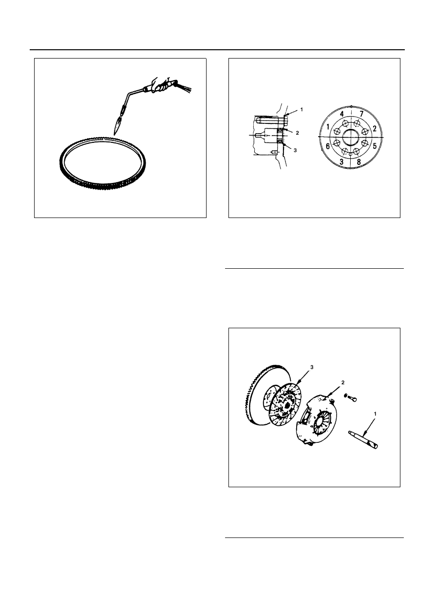
2. Install the ring gear when it is sufficiently heated.

The ring gear must be installed with the chamfer
facing the clutch.

Pilot Bearing
Check the pilot bearing for wear or damage and replace
with a new one if any abnormal condition is noticeable.

Installation

1. Pilot Bearing
2. Snap Ring
3. Flywheel Assembly
4. Washer

1) Align the flywheel with the crankshaft knock pin

and temporarily tighten the flywheel bolts.

2) Use the crankshaft stopper to prevent the

crankshaft from turning.
Crankshaft stopper: 5-8840-2230-0

3) Install the washer and the flywheel bolts and

tighten to the specified torque in numerical or-
der show in the illustration.

Tighten:
Flywheel bolt to

• 1st step: 78 N

⋅m (8.0 kg⋅m/58 lb⋅ft)

• 2nd step: 90 — 120

°

4) Remove the crankshaft stopper.

5. Driven Plate

Use the clutch pilot aligner to install the driven
plate.
Clutch Pilot Aligner: 5-8840-2240-0

6. Clutch Pressure Plate Assembly

1) Align the clutch pressure plate with the flywheel

knock pin.

N6A0589E

Legend

1. Washer
2. Snap ring
3. Pilot bearing

Legend

1. Clutch pilot aligner
2. Clutch pressure plate assembly
3. Driven plate

N6A0586E

N6A0351E

ENGINE (4HF1 / 4HF1-2 / 4HE1-TC / 4HG1 / 4HG1-T) 6A3-97

2) Tighten the pressure plate bolts to the specified

torque in numerical order.

Tighten:
Clutch pressure plate bolt to 40 N

⋅m (4.1 kg⋅m/30 lb⋅ft)

7. Transmission Assembly

Above works refer to “ENGINE ASSEMBLY” sec-
tion in this manual.

8. Starter

Tighten:
Starter bolt to 76 N

⋅m (7.7 kg⋅m/56 lb⋅ft)

9. Transmission Panel

• Connect the battery ground cable.

Legend

A. Knock pin

N6A0352E

N6A0582E

6A3-98 ENGINE (4HF1 / 4HF1-2 / 4HE1-TC / 4HG1 / 4HG1-T)

CRANKSHAFT FRONT OIL SEAL

Component

Removal

Preparation

• Disconnect battery ground cable.
• Tilt the cab.
• Drain coolant

1. Transmission Panel
2. Starter

• Disconnect the battery cable at the starter mo-

tor.

• Remove the starter assembly from flywheel

housing.

Legend

1. Transmission panel (Australia only)

7. Fan assembly

2. Starter

8. Fan belt

3. Radiator upper hose

9. Crankshaft damper pulley

4. Coolant reserve tank hose/Bypass hose

10. Crankshaft front oil seal

5. Radiator lower hose

11. Crankshaft front slinger

6. Radiator (with guide)

N6A0595E

ENGINE (4HF1 / 4HF1-2 / 4HE1-TC / 4HG1 / 4HG1-T) 6A3-99

3. Radiator Upper Hose
4. Coolant Reserve Tank Hose/Bypass Hose
5. Radiator Lower Hose
6. Radiator (with Guide)
7. Fan Assembly

8. Fan Belt
9. Crankshaft Damper Pulley

1) Use the crankshaft stopper to prevent the

crankshaft from turning.
Crankshaft Stopper: 5-8840-2230-0

2) Loosen the damper pulley bolts and remove

the damper pulley.

10. Crankshaft Front Oil Seal

Caution:
Be careful not to damage the crankshaft oil seal contact
surface during the removal procedure.

11. Crankshaft Front Slinger

Use the slinger puller to pull out the slinger.
Slinger Puller: 5-8840-2360-0

N6A0582E

N6A0597E

Legend

1. Oil seal
2. Slinger
3. Felt

N6A0598E

N6A0599E


Content   ..  359  360  361  362   ..