Isuzu N-Series. Manual - part 360
6A3-92 ENGINE (4HF1 / 4HF1-2 / 4HE1-TC / 4HG1 / 4HG1-T)
14. Oil Pan
15. Spacer Rubber
Above works refer to “OIL PAN” section in this
manual.
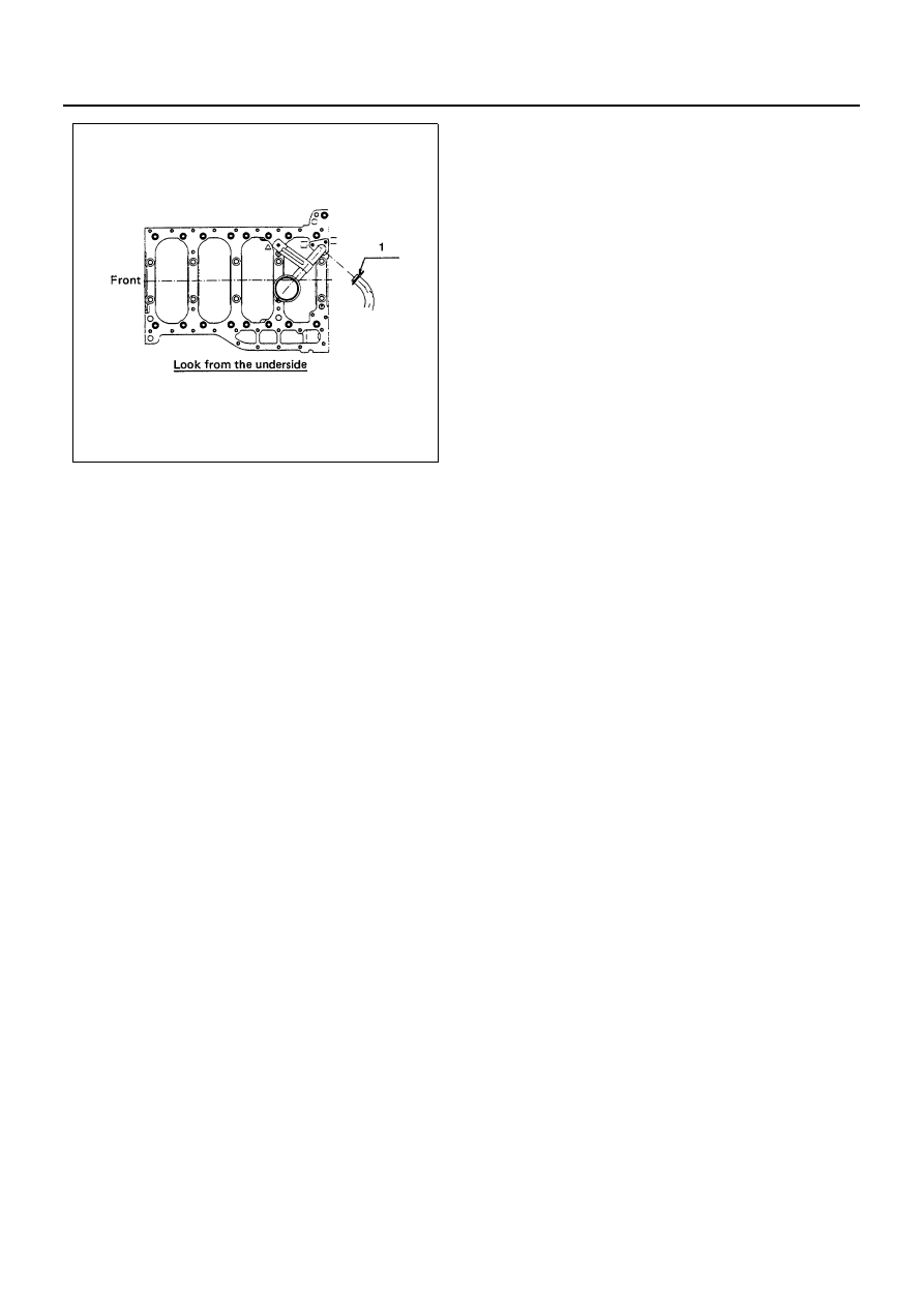
16. Nozzle Cover
• Pour engine oil and coolant into the engine
• Connect battery ground cable
• Start the engine and check for coolant and oil
leakage
N6A0580E