Isuzu N-Series. Manual - part 358
6A3-84 ENGINE (4HF1 / 4HF1-2 / 4HE1-TC / 4HG1 / 4HG1-T)
Notice:
Be careful not to fail to remove the bolts shown in the il-
lustration.
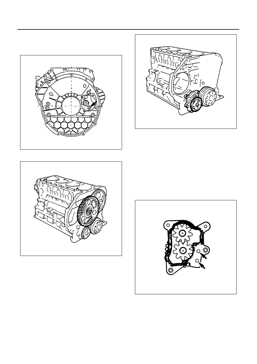
27. Idle Gear A
28. Oil Pump Assembly
Installation
1. Oil Pump Assembly
1) Carefully wipe any foreign material from the cyl-
inder body rear surface.
2) Apply the recommended liquid gasket (Three
Bond 1141E) or its equivalent to the shaded ar-
eas shown in the illustration.
Caution:
Be careful that no liquid gasket gets into the holes in the
arrow-marked portion in the illustration and the inside of
the oil pump cover.
3) Install the oil pump to the cylinder body.
4) Tighten the oil pump to the specified torque.
Tighten:
Oil pump bolt to 31 N
⋅m (3.2 kg⋅m/23 lb⋅ft)
N6A0432E
N6A0562E
N6A0177E
N6A0176E