Isuzu N-Series. Manual - part 323


  Index      Isuzu     Isuzu N-Series - service repair manual


Search            


Content   ..  321  322  323  324   ..


Isuzu N-Series. Manual - part 323


6A-34 ENGINE MECHANICAL

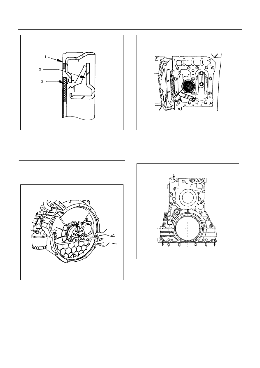
22. Crankshaft Rear Slinger

Use the slinger puller to pull out the slinger.
Slinger Puller: 5-8840-2360-0

23. Spacer Rubber
24. Oil Pan
25. Oil Pump Strainer
26. Water Pump Pulley
27. Water Pump

28. Front Retainer

Install the three front retainer fixing bolts to the
front retainer replacer holes as shown in the illus-
tration, and tighten the bolts alternately a little at a
time.

29. Oil Thermo Valve (4HF1, 4HF1-2, 4HG1, 4HG1-T)

Pull out the thermo valve from the cylinder body.

Legend

1. Oil seal
2. Slinger
3. Felt

N6A0187E

N6A0192E

N6A0193E

N6A0194E

ENGINE MECHANICAL 6A-35

30. Bypass Valve (4HE1-TC)

Pull out the bypass valve from the cylinder body.

31. Power Steering Pump Idle Gear Cover
32. Power Steering Pump Idle Gear
33. Flywheel Housing
34. Idle Gear A
35. Oil Pump Assembly

Above works refer to “OIL PUMP” section in this
manual.

36. Connecting Rod Cap Assembly
37. Connecting Rod Lower Bearing

1) Take out the connecting rod bearing cap bolts

and remove the bearing cap with the lower
bearing.

2) If the connecting rod lower bearings are to be

reinstalled, mark their fitting positions by tag-
ging each bearing with the cylinder number
from which it was removed.

38. Piston and Connecting Rod Assembly

1) To facilitate smooth removal of piston, remove

carbon from the upper part of the cylinder wall
using a scraper or equivalent.

2) Remove the piston and connecting rod assem-

bly upward by pushing on the edge of the con-
necting rod with a hammer handle or
equivalent.

3) If the connecting rod bearing are to be rein-

stalled, mark their fitting positions by tagging
each bearing with the cylinder number from
which it was removed.

Caution:
Do not bend or damage the oiling jet.

Notice:
When removing the piston and connecting rod assem-
bly, pull the connecting rod in parallel with the cylinder
bore.

39. Crankcase

1) Loosen the crankcase bolts in numerical order

a little at a time.

2) Install the three crankcase fixing bolts (See left

arrow marks) to the crankcase replacer holes
as shown in the illustration, and tighten the
bolts alternate a little at a time.

Notice:
When removing the crankcase, be sure to remove the oil
pump and the generator bracket before that.

N6A0195E

N6A0196E

N6A0197E

6A-36 ENGINE MECHANICAL

40. Thrust Bearing Lower
41. Crankshaft Bearing Lower

42. Crankshaft Assembly
43. Thrust Bearing Upper
44. Crankshaft Bearing Upper

45. Crankshaft Gear

1) Use the crankshaft gear remover to remove the

crankshaft gear.
Crankshaft Gear Remover: 8-9439-6818-0

2) Remove the crankshaft feather key.

46. Crankshaft

Inspection and Repair

Make the necessary adjustments, repairs, and part re-
placements if excessive wear or damage is discovered
during inspection.
Crankshaft End Play

1. Set the dial indicator to the crankshaft end and

measure the end play.

2. If the measured value exceeds the specified limit,

the thrust bearings must be replaced.

N6A0198E

N6A0199E

N6A0201E

N6A0202E

ENGINE MECHANICAL 6A-37

Crankshaft and Bearing

Inspect the surface of the crankshaft journals and crank-
pins for excessive wear and damage.
Inspect the oil seal fitting surfaces for excessive wear
and damage.
Inspect the oil ports for obstructions.
Crankshaft Run-Out

1. Set a dial indicator to the center of the crankshaft

journal.

2. Gently turn the crankshaft in the normal direction of

rotation.

Read the dial indicator as you turn the crankshaft.
If the measured value exceeds the specified limit, the
crankshaft must be replaced.

Bearing Spread
Use a vernier caliper to measure the bearing spread.
If the measured value is less than the specified limit, the
bearing must be replaced.

Crankshaft Journal and Crankpin Diameter

1. Use a micrometer to measure the crankshaft jour-

nal diameter across points (1) — (1) and (2) — (2).

2. Use the micrometer to measure the crankshaft

journal diameter at the two points (3) and (4).

Crankshaft End Play

mm (in)

Standard

Limit

0.104 — 0.205 (0.0041 

— 0.0081)

0.35 (0.014)

Crankshaft Run-Out

mm (in)

Standard

Limit

0.05 (0.002) or less

0.30 (0.012)

N6A0203E

Bearing Spread

mm (in)

Limit

87 (3.43)

N6A0204E

N6A0205E


Content   ..  321  322  323  324   ..