Isuzu N-Series. Manual - part 321
6A-26 ENGINE MECHANICAL
7. Cotter Pin
8. Spring Seat
9. Oil Relief Valve Spring
10. Oil Relief Valve
11. Pump Cover
Inspection and Repair
Make the necessary adjustments, repairs, and part re-
placements if excessive wear or damage is discovered
during inspection.
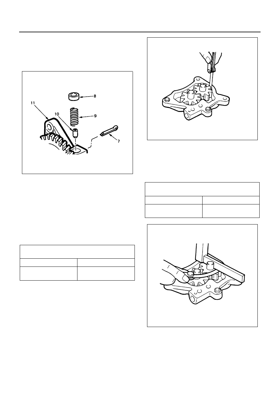
Gear Teeth and Cover Inner Wall Clearance
Use a feeler gauge to measure the clearance between
the gear teeth and the cover inner wall.
If the clearance between the gear teeth and the cover in-
ner wall exceeds the specified limit, the oil pump assem-
bly must be replaced.
Gear and Cover Clearance
Use a feeler gauge to measure the clearance between
the cover and the gear.
If the clearance between the gear and the cover ex-
ceeds the specified limit, the oil pump assembly must be
replaced.
Driven Gear Shaft and Bushing Clearance
1. Use a micrometer to measure the gear shafts out-
side diameter.
Gear Teeth and Cover
Inner Wall Clearance
mm (in)
Standard
Limit
0.125 — 0.220 (0.0049
— 0.0087)
0.3 (0.012)
N6A0169E
Gear and Cover Clear-
ance
mm (in)
Standard
Limit
0.064 — 0.109 (0.0025
— 0.0043)
0.2 (0.008)
N6A0170E
N6A0171E