Isuzu N-Series. Manual - part 319


  Index      Isuzu     Isuzu N-Series - service repair manual


Search            


Content   ..  317  318  319  320   ..


Isuzu N-Series. Manual - part 319


6A-18 ENGINE MECHANICAL

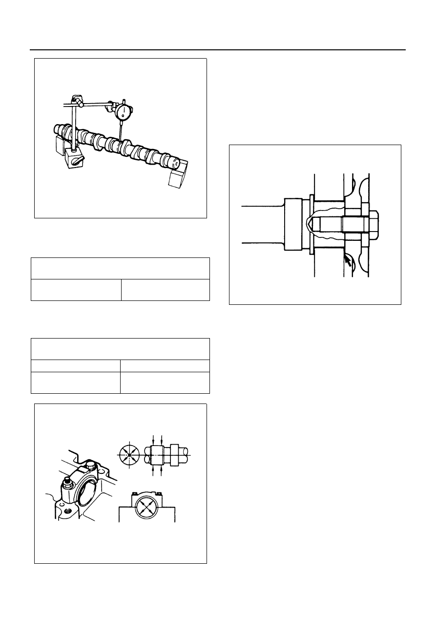
Camshaft and Camshaft Bearing Clearance

Use an inside dial indicator to measure the camshaft
bearing inside diameter.

If the clearance between the camshaft bearing inside di-
ameter and the journal exceeds the specified limit, the
camshaft bearing must be replaced.

Reassembly

1. Key
2. Camshaft Gear

• With the projection of the camshaft gear center

boss turned to the camshaft side, set it to the knock
pin and install the camshaft gear.

Tighten:
Camshaft gear bolt to 142 N

⋅m (14.5 kg⋅m / 105 lb⋅ft)

3. Camshaft Bearing Lower
4. Camshaft Assembly
5. Camshaft Bearing Upper
6. Camshaft Bearing Cap
7. Valve Cap
8. Rocker Arm Shaft Assembly

Above works refer to “CYLINDER HEAD” section
in this manual.

Camshaft Bearing Inside 
Diameter

mm (in)

Standard

40.000 — 40.037 

(1.5748 — 1.5763)

Camshaft Bearing Clear-
ance

mm (in)

Standard

Limit

0.025 — 0.087 (0.00098 

— 0.00343)

0.15 (0.0059)

N6A0147E

N6A0148E

N6A0149E

ENGINE MECHANICAL 6A-19

ROCKER ARM ASSEMBLY

Component

Disassembly

1. Rocker Arm Shaft Assembly

1) Loosen the rocker arm shaft bracket nuts and

bolts in numerical order a little at a time and re-
move the rocker arm shaft assembly with the
camshaft brackets.

2) Leave the (1) indicated bolt unremoved on this

occasion, since it is the rocker arm fixing bolt.

Caution:
Failure to loosen the rocker arm shaft bracket nuts and
bolts in numerical order a little at a time will adversely af-
fect the rocker arm shaft.

2. Valve Cap

Caution:
Take sufficient care not to let the valve caps fall into the
gear case or oil return hole.

3. Camshaft Bracket
4. Rocker Arm
5. Spring
6. Rocker Arm Bracket
7. Camshaft Bracket

Legend

1. Rocker arm shaft assembly

5. Spring

2. Valve cap

6. Rocker arm bracket

3. Camshaft bracket

7. Camshaft bracket

4. Rocker arm

8. Rocker arm shaft

N6A0150E

N6A0150E

6A-20 ENGINE MECHANICAL

8. Rocker Arm Shaft

Inspection and Repair

Make the necessary adjustments, repairs, and part re-
placements if excessive wear or damage is discovered
during inspection.

Rocker Arm Shaft Run-Out

1) Place the rocker arm shaft on V-blocks.
2) Use a dial indicator to measure the rocker arm

shaft central portion run-out.
If the run-out is very slight, correct the rocker
arm shaft run-out with a bench press. The rock-
er arm must be at cold condition.
If the measured rocker arm shaft run-out ex-
ceeds the specified limit, the rocker arm shaft
must be replaced.

Rocker Arm Shaft Outside Diameter

Use a micrometer to measure the rocker arm fitting por-
tion outside diameter.
If the measured value is less than the specified limit, the
rocker arm shaft must be replaced.

Rocker Arm Bushing Inside Diameter

Use either a vernier caliper or a dial indicator to measure
the rocker arm bushing inside diameter.

Check to see if the rocker arm oil port is free of obstruc-
tions.

Rocker Arm Shaft Run-Out

mm (in)

Limit

0.3 (0.012)

Rocker Arm Shaft Out-
side Diameter

mm (in)

Standard

Limit

21.979 — 22.000 

(0.8653 — 0.8661)

21.85 (0.8602)

N6A0152E

Rocker Arm Bushing 
Inside Diameter

mm (in)

Standard

Limit

22.010 — 22.035 

(0.8665 — 0.8675)

22.15 (0.8720)

Rocker Arm and Rocker 
Arm Shaft Clearance

mm (in)

Standard

Limit

0.010 — 0.056 (0.0004 

— 0.0022)

0.2 (0.0079)

N6A0153E

N6A0154E

ENGINE MECHANICAL 6A-21

If necessary, use compressed air to clean the rocker
arm oil port.

Rocker Arm Roller and Rocker Arm Pin

1. Pass a string through the rocker arm-roller clear-

ance and measure the roller protrusion while pull-
ing both ends of the string in the arrow-indicated
directions to push out the roller.

2. Mark the measuring point and draw out the string.

Measure the roller protrusion again while the roller
is pushed in.

3. Note the difference in the above measurements is

the standard roller-rocker arm pin clearance.
Should the clearance exceed the limit, replace the
rocker arm.

Valve Cap Wear

Inspect the valve cap surface contacting the rocker arm
using a dial gauge.
If wear exceeds the limit, replace the valve cap with a
new one.

Rocker Arm Roller and 
Pin Clearance

mm (in)

Standard

Limit

0.040 — 0.084 (0.0016 

— 0.0033)

0.5 (0.02)

N6A0155E

N6A0156E

Legend

1. Roller
2. Depth gauge

Valve Cap Worn

mm (in)

Limit

0.1 (0.004)

N6A0157E


Content   ..  317  318  319  320   ..