Isuzu N-Series. Manual - part 318


  Index      Isuzu     Isuzu N-Series - service repair manual


Search            


Content   ..  316  317  318  319   ..


Isuzu N-Series. Manual - part 318


6A-14 ENGINE MECHANICAL

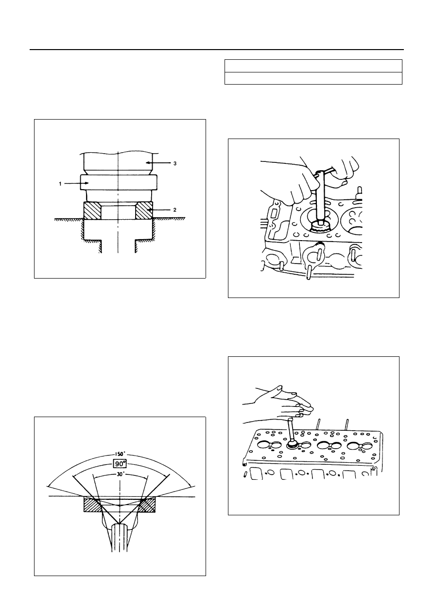
2. Use a bench press (3) to gradually apply pressure

to the attachment and press the valve seat insert
into place.

Caution:
Do not apply an excessive amount of pressure with the
bench press. Damage to the valve seat insert will result.

3. The valve should be lapped before final assembly

to ensure a good valve seal.
Above works refer to “Valve Seat Insert Correction”
section in this manual.

Valve Seat Insert Correction

1. Remove the carbon from the valve seat insert sur-

face.

2. Use a valve cutter (15

°, 45°, and 75° blades) to

minimize scratches and other rough areas. This
will bring the contact width back to the standard
value. Remove only the scratches and rough ar-
eas. Do not cut away too much. Take care not to
cut away unblemished areas of the valve seat sur-
face.

Notice:
Use an adjustable valve cutter pilot.
Do not allow the valve cutter pilot to wobble inside the
valve guide.

3. Apply abrasive compound to the valve seat insert

surface.

4. Insert the valve into the valve guide.
5. Turn the valve while tapping it to fit the valve seat

insert.

6. Check to see if the valve contact width is correct.
7. Check to see if the valve seat insert surface is in

contact with the entire circumference of the valve.

Reassembly

1. Spring Lower Seat

N6A0134E

N6A0135E

Valve Seat Angle

Degrees

45

°

N6A0136E

N6A0137E

ENGINE MECHANICAL 6A-15

2. Valve Guide Seal

1) Apply a coat of engine oil to the valve guide

seal inner face.

2) Use a valve guide seal installer to install the

valve guide seal to the valve guide
Valve Guide Seal Installer: 8-9439-6815-0

3. Intake and Exhaust Valve

1) Apply a coat of engine oil to each valve stem

before installation.

2) Install the intake and exhaust valve.

3) Turn the cylinder head up to install the valve

spring. Take care not to allow the installed
valves to fall free.

4. Valve Spring

Install the valve spring with its fine pitched (or
painted) end side down.

5. Spring Upper Seat
6. Cotter Collar

1) Use the valve spring compressor to push the

valve spring into position.
Valve Spring Compressor: 5-8840-2228-0

2) Install the cotter collar to the valve stem.
3) Set the cotter collar by tapping around the head

of the collar with a rubber hammer.

N6A0138E

N6A0139E

N6A0140E

N6A0141E

6A-16 ENGINE MECHANICAL

CAMSHAFT

Component

Disassembly

1. Rocker Arm Shaft Assembly
2. Valve Cap
3. Camshaft Bearing Cap
4. Camshaft Bearing Upper
5. Camshaft Assembly
6. Camshaft Bearing Lower

Above works refer to “CYLINDER HEAD” section
in this manual.

7. Camshaft Gear

Use the universal puller to pull out the camshaft
gear.
Universal puller: 5-8840-2027-0/5-8840-0086-0

8. Key

Legend

1. Rocker arm shaft assembly

5. Camshaft assembly

2. Valve cap

6. Camshaft bearing lower

3. Camshaft bearing cap

7. Camshaft gear

4. Camshaft bearing upper

8. Key

N6A0142E

N6A0143E

ENGINE MECHANICAL 6A-17

Inspection and Repair

Make the necessary adjustments, repairs, and part re-
placements if excessive wear or damage is discovered
during inspection.

Camshaft End Play

Use a thickness gauge to measure the clearance be-
tween the camshaft gear (1) and the camshaft bracket
(2).
If the measured value exceeds the specified limit, the
camshaft gear or the camshaft must be replaced.

Camshaft Journal Diameter

Use a micrometer to measure each camshaft journal di-
ameter in two directions ((1) and (2)). If the measured
value is less than the specified limit, the camshaft must
be replaced.

Cam Height

Measure the cam height “H” with a micrometer. If the
measured value is less than the specified limit, the cam-
shaft must be replaced.

Camshaft Run-Out

1. Mount the camshaft on V-blocks.
2. Measure the run-out with a dial indicator.

If the measured value exceeds the specified limit,
the camshaft must be replaced.

Camshaft End Play

mm (in)

Standard

Limit

0.085 — 0.205 (0.0033 

— 0.0081)

0.25 (0.0098)

Camshaft Journal Diam-
eter

mm (in)

Standard

Limit

39.950 — 39.975 

(1.5728 — 1.5738)

39.850 (1.569)

N6A0144E

Cam Height “H”

mm (in)

Engine model

Standard

Limit

Except 4HE1-

TC

52.8 (2.078)

51.8 (2.039)

4HE1-TC

53.6 (2.110)

52.6 (2.071)

Camshaft Run-Out

mm (in)

Limit

0.05 (0.002)

N6A0145E

N6A0146E


Content   ..  316  317  318  319   ..