Isuzu N-Series. Manual - part 316
6A-6 ENGINE MECHANICAL
2) Apply a coat of engine oil to the bearing cap
bolt and stud threads.
3) Tighten the bearing cap bolts and studs to the
specified torque.
Tighten:
Camshaft bearing cap nut and bolt to 27 N
⋅m (2.8 kg⋅m
/ 20 lb
⋅ft)
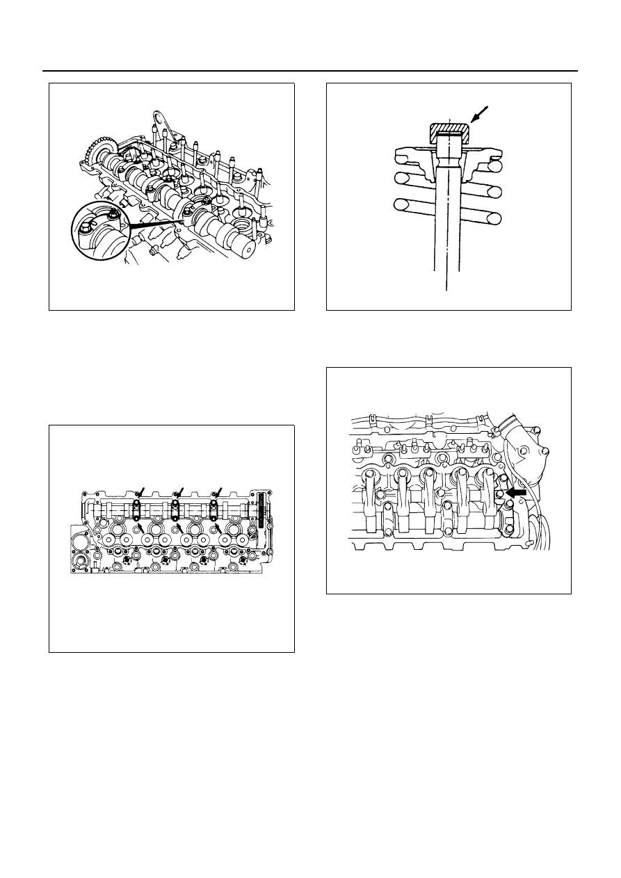
6. Valve Cap
Apply engine oil to the inside of the valve caps and
install them to the valve stem end.
Caution:
Take sufficient care not to let valve caps fall into the
gear.
7. Rocker Arm Shaft Assembly
1) Temporarily tighten the bolts marked with the
arrow in the illustration.
2) Loosen the rocker arm adjust screws and apply
engine oil to the rocker arm roller portions.
3) Install the rocker arm assembly on the cylinder
head.
4) Tighten the rocker arm shaft bracket nuts and
bolts to the specified torque in numerical order
a little at a time as shown in the illustration.
Tighten:
Rocker arm shaft bracket nut and bolt to
• Nut (A): 27 N
⋅m (2.8 kg⋅m / 20 lb⋅ft)
• Bolt (B): 56 N
⋅m (5.7 kg⋅m / 41 lb⋅ft)
• Bolt (C): 27 N
⋅m (2.8 kg⋅m / 20 lb⋅ft)
N6A0109E
N6A0110E
N6A0111E
N6A0112E