Isuzu N-Series. Manual - part 1029


  Index      Isuzu     Isuzu N-Series - service repair manual


Search            


Content   ..  1027  1028  1029  1030   ..


Isuzu N-Series. Manual - part 1029


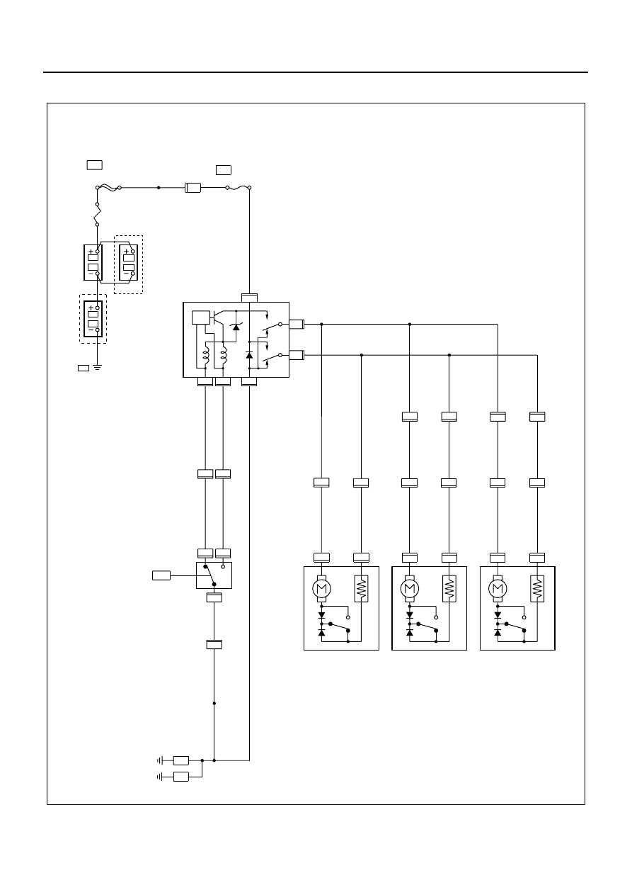
CAB AND CHASSIS ELECTRICAL 8-221

Circuit Diagram

2

3

1

2

3

6

5

4

4

2

H-11

H-11

1

B-12

B-12

B-12

B-12

B-12

B-12

D-4

D-4

D-4

2

1

2

1

1

2

2

3

1

2

1

D-8

D-8

D-9

D-9

H-18

D-10

D-10

H-11

B-7

FL-1 100A or 120A

MAIN

AUDIO, DOOR LOCK

5W

RELAY:
DOOR LOCK

0.3R/G

0.3G/B

0.3R/G

0.3G/B

DOOR LOCK SW-LH

0.3B

2B

3B

HEADLIGHT BRACKET (LH)

0.85B

0.85BR/R

0.85BR/Y

0.85BR/R

0.85BR/Y

0.85BR/R

0.85BR/Y

0.85BR/R

0.85BR/Y

0.5BR/R

0.5BR/Y

0.5BR/R

0.5BR/Y

DOOR LOCK 
ACTUATOR-RH

DOOR LOCK
ACTUATOR-LH
(CREW CAB)

  (24V 
   MODEL)

P-5

P-3

P-4

P-1

P-2

F-4   15A

H-6

3W/B

2

H-18

H-19

H-19

H-12

H-12

H-3

H-3

4

1

13

5

FRAME

0.85BR/R

0.85BR/R

0.85BR/Y

0.85BR/Y

UNLOCK

LOCK

UNLOCK

UNLOCK

UNLOCK

LOCK

LOCK

LOCK

4

3

H-2

H-2

DOOR LOCK
ACTUATOR-RH
(CREW CAB)

B-1

5B

FRAME-LH (FRONT)

0.85R

2L

P-3

P-4

4JH1

8W/B(12V)

5W/B(24V)

N8A0213E

8-222 CAB AND CHASSIS ELECTRICAL

Connector List

No.

Connector Face

B-12

D-4

D-4

D-8

D-8

D-9

D-9

D-10

006-010

1

2

3

4

5

6

003-003

1

2

3

003-011

3

2

1

002-001

1

2

002-002

1

2

002-001

1

2

002-002

1

2

002-001

1

2

D-10

H-18

H-18

H-19

H-19

H-2

H-2

H-11

No.

Connector Face

002-002

1

2

002-001

1

2

002-002

1

2

002-001

1

2

002-002

1

2

008-009

1 2

3

8

4 5 6 7

008-010

1

2

3

8

4

5

6

7

008-009

1 2

3

8

4 5 6 7

CAB AND CHASSIS ELECTRICAL 8-223

H-6

H-11

H-3

H-3

H-12

H-12

P-1

(12 V)

P-2

P-1

(24 V)

No.

Connector Face

008-010

1

2

3

8

4

5

6

7

006-014

1

2

3

4

5

6

006-015

1

2

3

4

5

6

014-002

1 2 3

7 8 9 10

11

4

12

5

13

6

14

014-003

6 5 4

1413 12 11

3 2 1

9 8 7

10

000-003

000-004

000-004

P-4

P-2

(24 V)

P-3

P-5

(12 V)

P-5

(24 V)

No.

Connector Face

000-004

000-006

000-006

000-007

000-002

1

2

1

2

1 2 3 4

5 6 7 8

9 10 11 12 13

14 15 16 17 18

2

1

2

1

4 3 2 1

8 7 6 5

13 12 11 10 9

18 17 16 15 14

H - 6

H - 7

H - 8

N8A5489E

8-224 CAB AND CHASSIS ELECTRICAL

Diagnosis

Quick Chart for Check Point

Notice:
Figure in parenthesis “( )” indicates the order of inspection.

Check point

Fuse

F-4

(15 A)

Door lock 

controller

Door 

lock SW 

(Driver 

side)

Door lock actuator

Front 

(Passen-

ger side)

Rear

(RH)

Rear

(LH)

Cable 

harness

Trouble
mode

1. All the doors do not lock 
and unlock

2. All the doors do not get 
locked (or unlocked)

3. Driver side door does not 
get locked (or unlocked)

4. Front passenger side 
door does not get locked (or 
unlocked)

5. Rear door-RH side does 
not get locked (or unlocked)

6. Rear door-LH side does 
not get locked (or unlocked)


Content   ..  1027  1028  1029  1030   ..