Isuzu N-Series. Manual - part 1030


  Index      Isuzu     Isuzu N-Series - service repair manual


Search            


Content   ..  1028  1029  1030  1031   ..


Isuzu N-Series. Manual - part 1030


CAB AND CHASSIS ELECTRICAL 8-225

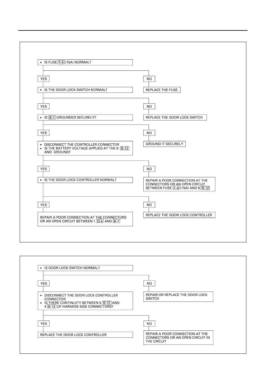
All the Doors Do Not Lock and Unlock

All the Doors Do Not Get Locked (or Unlocked)

N8A5256E

N8A5257E

8-226 CAB AND CHASSIS ELECTRICAL

Driver Side Door Does Not Get Locked (or Unlocked)

FRT Passenger Side Door Does Not Get Locked (or Unlocked)
RR Door-RH Side Does Not Get Locked (or Unlocked)
RR Door-LH Side Does Not Get Locked (or Unlocked)

REPLACE THE DOOR LOCK SWITCH

N8A0216E

REPLACE THE DOOR LOCK ACTUATOR

N8A0217E

CAB AND CHASSIS ELECTRICAL 8-227

Inspection of The Door Lock Circuit
Check the voltage and the continuity between the controller harness side connector terminals.

Termi-

Item

Connect-

Wire

nal

Connected to

to be

ing

Checking conditions

Standard

color

No.

checked

terminal

Unlock

Continuity

1

R/G

1-Ground

Lock

No continuity

Unlock

No continuity

2

G/B

2-Ground

Lock

Continuity

3

B

Ground

3-Ground

-

Continuity

Continuity

4

BR/Y

Actuator

4-5

-

(There is some

(Unlock)

resistance)
Continuity

5

BR/R

Actuator

5-4

-

(There is some

(Lock)

resistance)

6

R

Fuse F-7 (15A)

Voltage

6-Ground

-

Battery voltage

Conti-

nuity

(Resis-

tance)

Door lock SW
(Unlock)

Door lock SW
(Lock)

Driver seat side
door

Driver seat side
door

Harness side

1

2

3

4

5

6

B-12

N8A0218E

8-228 CAB AND CHASSIS ELECTRICAL

Door Lock Relay
The door lock controller sends out to each door lock ac-
tuator the lock/unlock signals received from door lock
switch of driver seat side.

Inspection
Remove the connector of the door lock controller, and
check the continuity and the voltage between the con-
troller side connector terminals.
(Connect the (+) terminal of the battery to 6 

 and

the (

−) terminal to 3 

.)

 — 5 

.................Continuity

 — 4 

.................Continuity

(Then, ground 2 

.)

..................Voltage for approx. 1 second

(Disconnect the ground of 2 

, and ground 1 

.)

..................Voltage for approx. 1 second

Replace the controller when the result of inspection is
found abnormal.

Door Lock Operation Test
After confirming that there is continuity between the har-
ness side connector terminals 4 

 and 5 

 of the

door lock controller, apply battery voltage to each of the
terminals to conduct the operation test.
When the door lock will not operate, check the door lock
actuator for any trouble.

For 24 Volt

For 12V

N8A0219E

B-12

B-12

B-12

B-12

B-12

B-12

B-12

B-12

B-12

B-12

B-12

B-12

Controller side

3

2

1

6

5

4

N8A0220E

B-12

B-12

Connecting terminal

4 (BR/Y)

5 (BR/R)

Operation

Unlock

Lock

Harness
side

1

2

3

4

5

6

B-12

N8A0221E


Content   ..  1028  1029  1030  1031   ..