Infiniti I30 (A33). Manual - part 136
2
CHECK CONNECTOR
1. Disconnect control unit connectors. Check terminals for damage or loose connections. Then reconnect connectors.
2. Carry out self-diagnosis again.
Does warning lamp activate again?
Yes
©
GO TO 3.
No
©
INSPECTION END
3
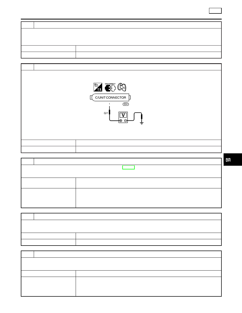
CHECK ABS CONTROL UNIT POWER SUPPLY
1. Disconnect control unit connector.
2. Check voltage between control unit connector terminal 1 and ground.
SBR726DF
Does battery voltage exist when ignition switch is turned ON?
Yes
©
GO TO 4.
No
©
GO TO 5.
4
CHECK CONTROL UNIT GROUND
Refer to CONTROL UNIT GROUND in Ground Circuit Check, BR-104.
Is ground circuit OK?
OK
©
Check control unit pin terminals for damage or the connection of control unit harness
connector. Reconnect control unit harness connector. Then retest.
NG
©
Check the following.
I
Harness connector E91
I
Harness for open or short between control unit and ground
If NG, repair harness or connectors.
5
CHECK FUSE
Check 10A fuse 31 (Engine control) for control unit. Refer to POWER SUPPLY ROUTING in EL section.
Is fuse OK?
Yes
©
GO TO 6.
No
©
Replace fuse.
6
CHECK ABS CONTROL UNIT POWER SUPPLY CIRCUIT
Check continuity between battery and control unit connector terminal 1.
Does continuity exist?
Yes
©
Check battery. Refer to BATTERY in EL section.
No
©
Check the following.
I
Harness connector E91
I
Harness for open or short between control unit and fuse
If NG, repair harness or connectors.
GI
MA
EM
LC
EC
FE
AT
AX
SU
ST
RS
BT
HA
SC
EL
IDX
TROUBLE DIAGNOSES FOR SELF-DIAGNOSTIC ITEMS
TCS
Low Voltage (Cont’d)
BR-127