Infiniti I30 (A33). Manual - part 70
CAUTION:
I
Install key interlock cable in such a way that it will not be
damaged by sharp bends, twists or interference with adja-
cent parts.
I
After installing key interlock cable to control device, make
sure that casing cap and bracket are firmly secured in
their positions. If casing cap can be removed with an
external load of less than 39.2 N (4.0 kg, 8.8 lb), replace
key interlock cable with new one.
SAT650J
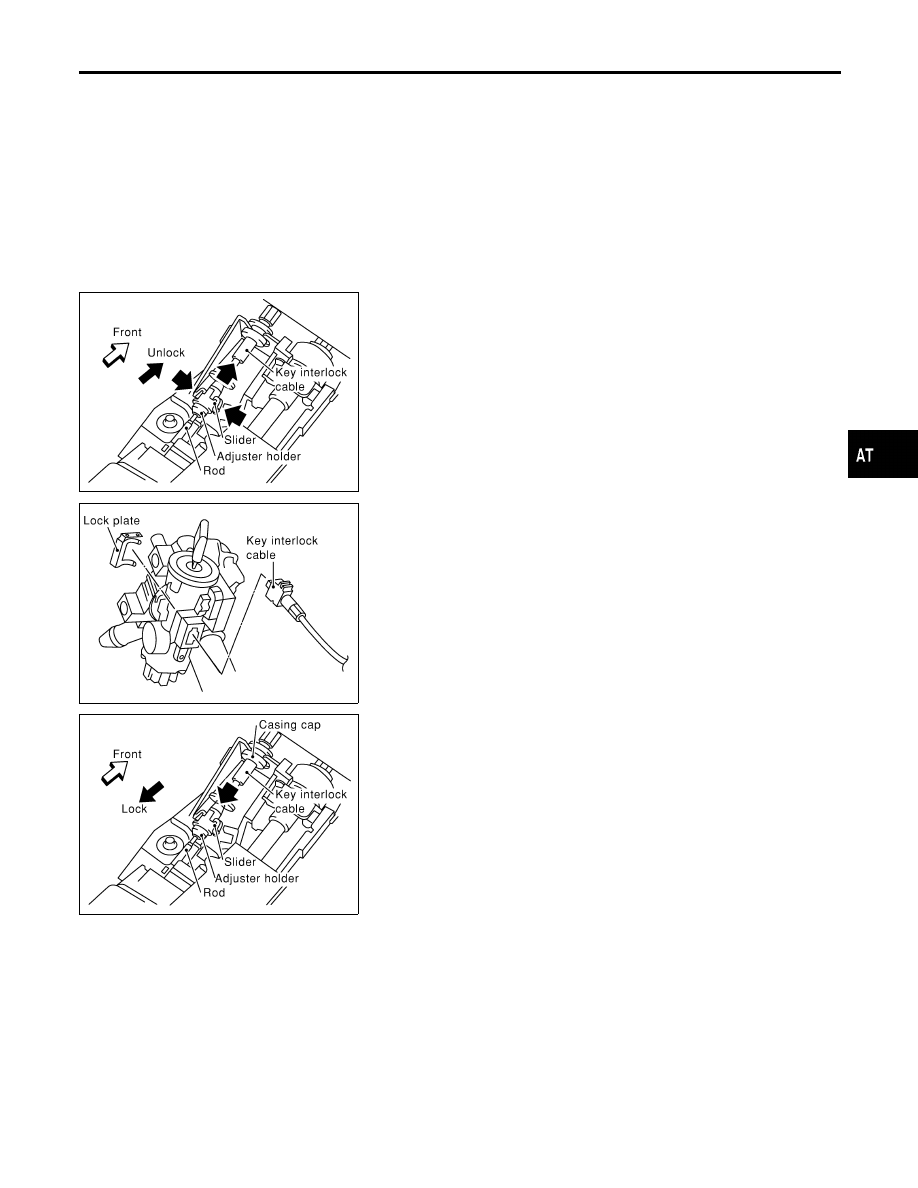
REMOVAL
NHAT0113S01
Unlock slider from adjuster holder and remove rod from cable.
SAT751J
INSTALLATION
NHAT0113S02
1.
Set key interlock cable to steering lock assembly and install
lock plate.
2.
Clamp cable to steering column and fix to control cable with
band.
3.
Set control lever to P position.
SAT752J
4.
Insert rod into adjuster holder.
5.
Install casing cap to bracket.
6.
Move slider in order to fix adjuster holder to rod.
GI
MA
EM
LC
EC
FE
AX
SU
BR
ST
RS
BT
HA
SC
EL
IDX
A/T SHIFT LOCK SYSTEM
Key Interlock Cable (Cont’d)
AT-277