Infiniti I30 (A33). Manual - part 44
 

  Index      Infiniti     Infiniti I30 (A33) - service repair manual 2001 year


Search            


Content   ..  42  43  44  45   ..


Infiniti I30 (A33). Manual - part 44


SAT014K

SEF949Y

Diagnostic Trouble Code (DTC) Confirmation
Procedure

NHAT0236

CAUTION:

Always drive vehicle at a safe speed.
NOTE:
If “DTC Confirmation Procedure” has been previously conducted,
always turn ignition switch OFF and wait at least 5 seconds before
conducting the next test.
After the repair, perform the following procedure to confirm the
malfunction is eliminated.

WITH CONSULT-II

NHAT0236S01

1)

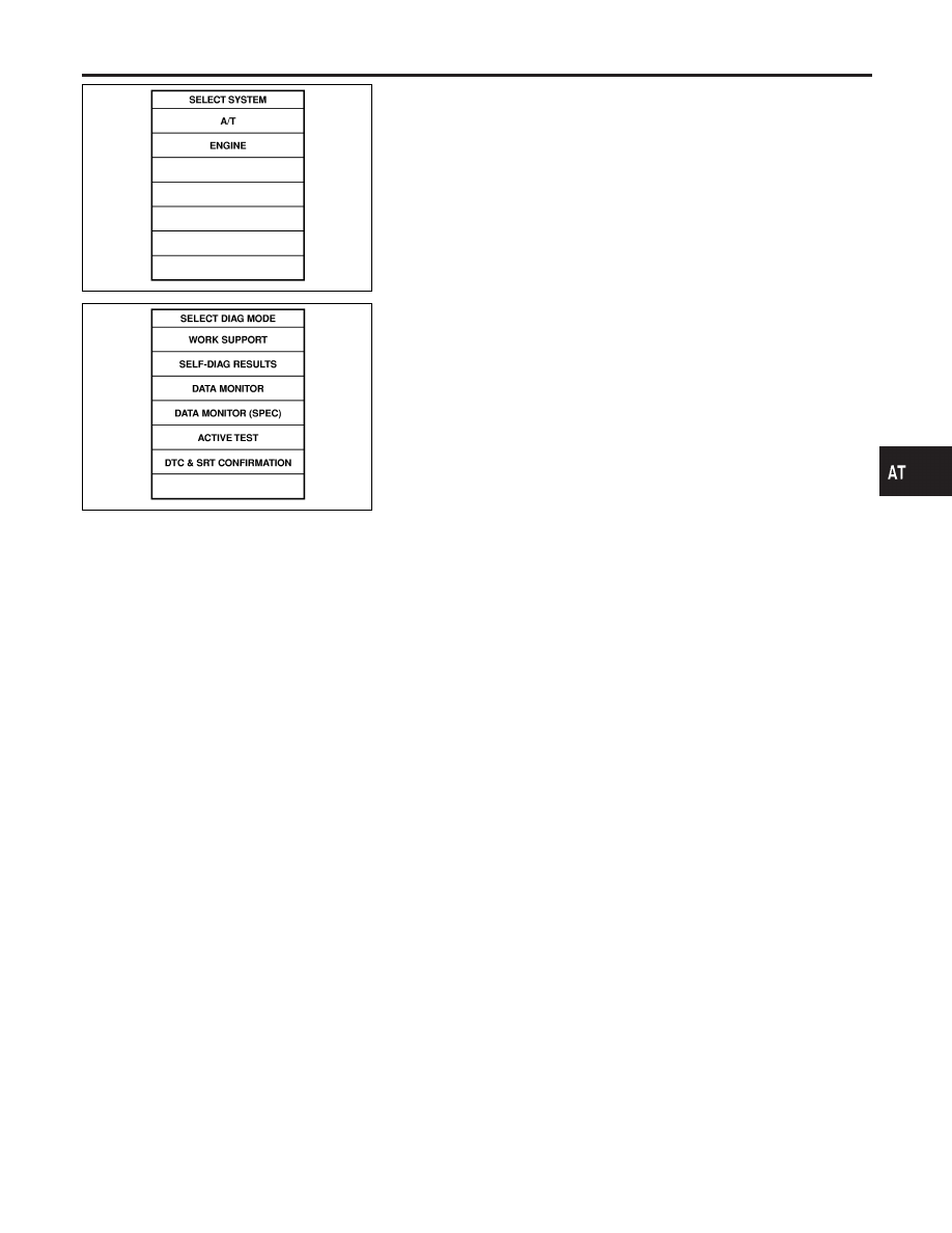
Turn ignition switch ON and select “DATA MONITOR” mode for
“ENGINE” with CONSULT-II.

2)

Start engine.

3)

Drive vehicle in D position and allow the transmission to shift
1

,

2 (“GEAR”).

WITH GST

NHAT0236S02

Follow the procedure “With CONSULT-II”.

GI

MA

EM

LC

EC

FE

AX

SU

BR

ST

RS

BT

HA

SC

EL

IDX

DTC P0750 SHIFT SOLENOID VALVE A

Diagnostic Trouble Code (DTC) Confirmation Procedure

AT-173

Wiring Diagram — AT — SSV/A

NHAT0068

MAT815A

SAT308K

DTC P0750 SHIFT SOLENOID VALVE A

Wiring Diagram — AT — SSV/A

AT-174

Diagnostic Procedure

NHAT0069

1

CHECK VALVE RESISTANCE

1. Turn ignition switch to OFF position.
2. Disconnect terminal cord assembly connector in engine compartment.
3. Check resistance between terminal 2 and ground.

SAT632JB

OK or NG

OK

©

GO TO 3.

NG

©

GO TO 2.

2

CHECK VALVE OPERATION

1. Remove control valve assembly. Refer to AT-280.
2. Check the following items:

I

Shift solenoid valve A

I

Operation check

i. Check solenoid valve by listening for its operating sound while applying battery voltage to the terminal and ground.

SAT035K

I

Harness of terminal cord assembly for short or open

OK or NG

OK

©

GO TO 3.

NG

©

Repair or replace damaged parts.

3

CHECK POWER SOURCE CIRCUIT

1. Turn ignition switch to OFF position.
2. Disconnect TCM harness connector.
3. Check continuity between sub-harness connector terminal 2 and TCM harness connector terminal 11. Refer to wiring

diagram — AT — SSV/A.

Continuity should exist.

If OK, check harness for short to ground and short to power.

4. Reinstall any part removed.

OK or NG

OK

©

GO TO 4.

NG

©

Repair open circuit or short to ground or short to power in harness or connectors.

GI

MA

EM

LC

EC

FE

AX

SU

BR

ST

RS

BT

HA

SC

EL

IDX

DTC P0750 SHIFT SOLENOID VALVE A

Diagnostic Procedure

AT-175

4

CHECK DTC

Perform Diagnostic Trouble Code (DTC) confirmation procedure, AT-173.

OK or NG

OK

©

INSPECTION END

NG

©

GO TO 5.

5

CHECK TCM INSPECTION

1. Perform TCM input/output signal inspection.
2. If NG, recheck TCM pin terminals for damage or loose connection with harness connector.

OK or NG

OK

©

INSPECTION END

NG

©

Repair or replace damaged parts.

DTC P0750 SHIFT SOLENOID VALVE A

Diagnostic Procedure (Cont’d)

AT-176


Content   ..  42  43  44  45   ..