Infiniti I30 (A33). Manual - part 14


  Index      Infiniti     Infiniti I30 (A33) - service repair manual 2001 year


Search            


Content   ..  12  13  14  15   ..


Infiniti I30 (A33). Manual - part 14


O/D OFF indicator lamp:

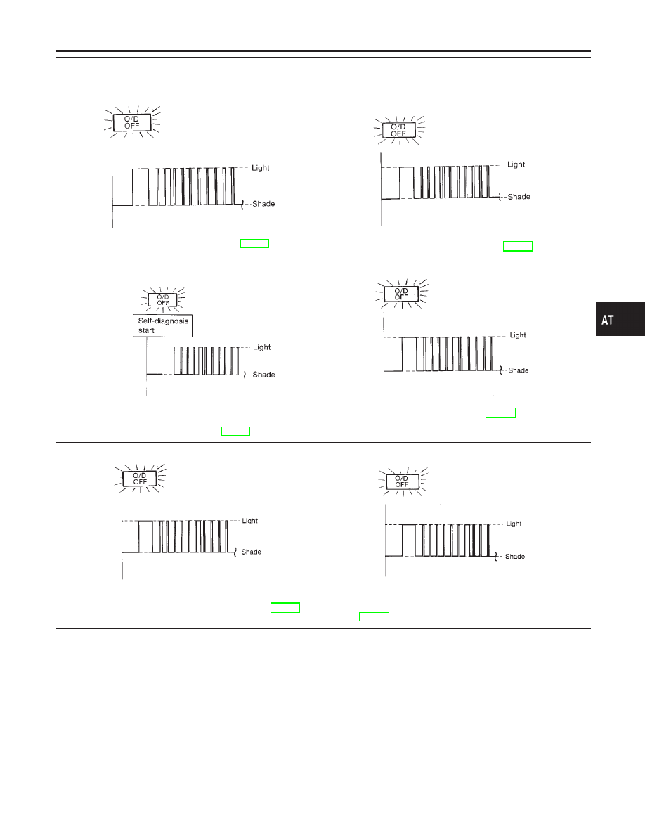
2nd judgement flicker is longer than others.

SAT439F

Vehicle speed sensor circuit is short-circuited or disconnected.

Go to VEHICLE SPEED SENSOR·MTR, AT-203.

3rd judgement flicker is longer than others.

SAT441F

Throttle position sensor circuit is short-circuited or disconnected.

Go to THROTTLE POSITION SENSOR, AT-182.

4th judgement flicker is longer than others.

SAT443F

Shift solenoid valve A circuit is short-circuited or disconnected.

Go to SHIFT SOLENOID VALVE A, AT-172.

5th judgement flicker is longer than others.

SAT445F

Shift solenoid valve B circuit is short-circuited or disconnected.

Go to SHIFT SOLENOID VALVE B, AT-177.

6th judgement flicker is longer than others.

SAT447F

Overrun clutch solenoid valve circuit is short-circuited or discon-
nected.

Go to OVERRUN CLUTCH SOLENOID VALVE, AT-191.

7th judgement flicker is longer than others.

SAT449F

Torque converter clutch solenoid valve circuit is short-circuited
or disconnected.

Go to TORQUE CONVERTER CLUTCH SOLENOID

VALVE, AT-151.

GI

MA

EM

LC

EC

FE

AX

SU

BR

ST

RS

BT

HA

SC

EL

IDX

ON BOARD DIAGNOSTIC SYSTEM DESCRIPTION

Diagnostic Procedure Without CONSULT-II (Cont’d)

AT-53

O/D OFF indicator lamp:

8th judgement flicker is longer than others.

SAT451F

A/T fluid temperature sensor is disconnected or TCM power
source circuit is damaged.

Go to A/T FLUID TEMPERATURE SENSOR AND TCM

POWER SOURCE, AT-196.

9th judgement flicker is longer than others.

SAT453F

Engine speed signal circuit is short-circuited or disconnected.

Go to ENGINE SPEED SIGNAL, AT-119.

10th judgement flicker is longer than others.

SAT455F

Line pressure solenoid valve circuit is short-circuited or discon-
nected.

Go to LINE PRESSURE SOLENOID VALVE, AT-166.

11th judgement flicker is longer than others.

SAT599J

The ECM-A/T communication line is open or shorted.

Go to A/T COMMUNICATION LINE, AT-208.

Lamp comes on.

SAT367J

Park/neutral position (PNP) switch, overdrive control switch or
throttle position switch circuit is disconnected or TCM is dam-
aged.

Go to 21. TCM Self-diagnosis Does Not Activate (Park/

neutral position (PNP), Overdrive Control and Throttle Posi-
tion Switch Circuit Checks), AT-260.

Flickers as shown below.

SAT457F

Battery power is low.
Battery has been disconnected for a long time.
Battery is connected conversely.
(When reconnecting TCM connectors. — This is not a problem.)

t

1

= 2.5 seconds t

2

= 2.0 seconds t

3

= 1.0 second t

4

= 1.0 second

ON BOARD DIAGNOSTIC SYSTEM DESCRIPTION

Diagnostic Procedure Without CONSULT-II (Cont’d)

AT-54

SAT631IA

Introduction

NHAT0024

SAT632I

SEF234G

The TCM receives a signal from the vehicle speed sensor, throttle
position sensor or park/neutral position (PNP) switch and provides
shift control or lock-up control via A/T solenoid valves.
The TCM also communicates with the ECM by means of a signal
sent from sensing elements used with the OBD-related parts of the
A/T system for malfunction-diagnostic purposes. The TCM is
capable of diagnosing malfunctioning parts while the ECM can
store malfunctions in its memory.
Input and output signals must always be correct and stable in the
operation of the A/T system. The A/T system must be in good
operating condition and be free of valve seizure, solenoid valve
malfunction, etc.
It is much more difficult to diagnose a problem that occurs intermit-
tently rather than continuously. Most intermittent problems are
caused by poor electric connections or improper wiring. In this
case, careful checking of suspected circuits may help prevent the
replacement of good parts.
A visual check only, may not find the cause of the problems. A road
test with CONSULT-II (or GST) or a circuit tester connected should
be performed. Follow the “Work Flow”. Refer to AT-59.
Before undertaking actual checks, take a few minutes to talk with
a customer who approaches with a driveability complaint. The cus-
tomer can supply good information about such problems, espe-
cially intermittent ones. Find out what symptoms are present and
under what conditions they occur. A “DIAGNOSITC WORKSHEET”
like the example (AT-56) should be used.
Start your diagnosis by looking for “conventional” problems first.
This will help troubleshoot driveability problems on an electronically
controlled engine vehicle.
Also check related Service bulletins for information.

GI

MA

EM

LC

EC

FE

AX

SU

BR

ST

RS

BT

HA

SC

EL

IDX

TROUBLE DIAGNOSIS — INTRODUCTION

Introduction

AT-55

DIAGNOSTIC WORKSHEET

=NHAT0024S01

Information from Customer

NHAT0024S0101

KEY POINTS
WHAT 
........ Vehicle & A/T model
WHEN ........ Date, Frequencies
WHERE ..... Road conditions
HOW .......... Operating conditions, Symptoms

Customer name

MR/MS

Model & Year

VIN

Trans. model

Engine

Mileage

Incident Date

Manuf. Date

In Service Date

Frequency

l

Continuous

l

Intermittent (

times a day)

Symptoms

l

Vehicle does not move.

(

l

Any position

l

Particular position)

l

No up-shift

(

l

1st

,

2nd

l

2nd

,

3rd

l

3rd

,

O/D)

l

No down-shift

(

l

O/D

,

3rd

l

3rd

,

2nd

l

2nd

,

1st)

l

Lockup malfunction

l

Shift point too high or too low.

l

Shift shock or slip

(

l

N

,

D

l

Lockup

l

Any drive position)

l

Noise or vibration

l

No kickdown

l

No pattern select

l

Others

(

)

O/D OFF indicator lamp

Blinks for about 8 seconds.

l

Continuously lit

l

Not lit

Malfunction indicator lamp (MIL)

l

Continuously lit

l

Not lit

TROUBLE DIAGNOSIS — INTRODUCTION

Introduction (Cont’d)

AT-56


Content   ..  12  13  14  15   ..