Hyundai Santa Fe (2006 year). Manual - part 764
RT -98
RESTRAINTS
DTC B1451 SIDE IMPACT SENSOR [REAR-DRIVER] CIRCUIT
SHORT TO GROUND
DTC B1454 SIDE IMPACT SENSOR [REAR-PASSENGER] CIRCUIT
SHORT TO GROUND
DTC DESCRIPTION
E2C1F3FE
The detecting system for side crash consists of the SRSCM and four Side Impact Sensors (SIS). The SRSCM sets above
DTC(s) if it detects short to ground on the SIS circuit.
DTC DETECTING CONDITION
EB5BE55B
DTC
Condition
Probable cause
B1451
B1454
• Short to ground between SIS and SRSCM
• Side Impact Sensor (SIS) Malfunction
• SRSCM Malfunction
• Short to ground circuit on
wiring harness
• Side Impact Sensor (SIS)
• SRSCM
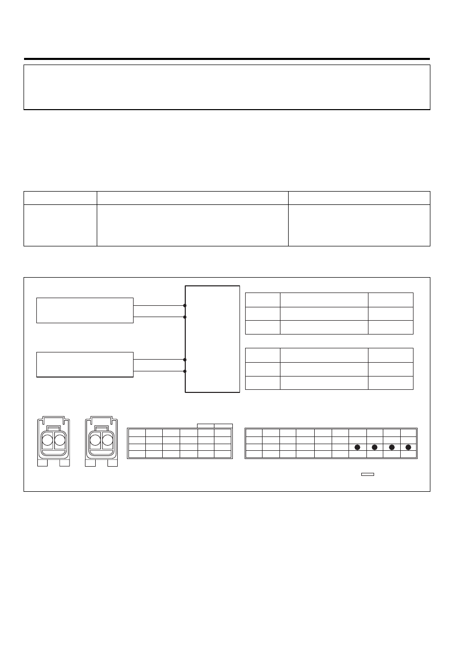
SCHEMATIC DIAGRAM
E2866786
[HARNESS CONNECTOR]
SIS[Driver] SIS[Passenger]
SRSCM
22(B)
SIS [Driver]
High
21(B)
23(B)
SIS [Passenger]
High
24(B)
Low
Low
1
2
1
2
Terminal
Terminal
Connected to
Function
Connected to
Function
1
SRSCM Terminal 22(B)
SIS High
2
SRSCM Terminal 21(B)
SIS Low
SIS High
SIS Low
SIS [Driver]
1
SRSCM Terminal 23(B)
2
SRSCM Terminal 24(B)
SIS [Passenger]
SIS High
SIS Low
SRSCM
CONNECTOR A
CONNECTOR B
Shorting Bar
10
9
8
7
6
5
4
3
2
1
20
19
18
17
16
15
14
13
12
11
30
29
28
27
26
25
24
23
22
21
40
39
38
37
36
35
34
33
32
31
6
5
4
3
2
1
12
11
10
9
8
7
18
17
16
15
14
13
24
23
22
21
20
19
1
2
1
2
SCMRT6170L
TERMINAL & CONNECTOR INSPECTION
E9E88BA8
Refer to the DESCRIPTION in this TROUBLESHOOTING section. (See page RT - 36)
INSPECTION PROCEDURE
E1588FE0
1.
PREPARATION
Refer to the DESCRIPTION in this TROUBLESHOOTING section. (See page RT - 36)
2.
CHECK SHORT TO GROUND