Hyundai Santa Fe (2006 year). Manual - part 760


  Index      Hyundai     Hyundai Santa Fe - service repair manual 2006 year


Search            


Content   ..  758  759  760  761   ..


Hyundai Santa Fe (2006 year). Manual - part 760


RT -82

RESTRAINTS

1)

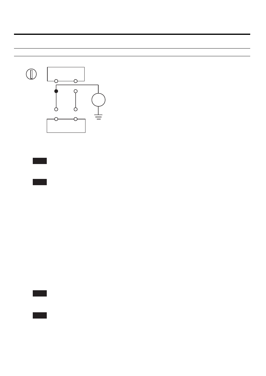
Measure resistance between the terminal 1 of SAB harness connector and chassis ground.

Specification (resistance) : infinite

SAB

SRSCM

LOCK

19(8)B

2

20(7)B

1

ERBF200J

2)

Is the measured resistance within specification?

YES

▶ Check the SAB Module.

NO

▶ Repair or replace the wiring harness between the SAB and the SRSCM.

3.

CHECK THE SAB MODULE

1)

Replace the Side Airbag(SAB) with a new one.
● Refer to "Side Airbag(SAB)" section in this SERVICE MANUAL.

2)

Install the DAB module and connect the DAB connector.

3)

Connect the connectors of the PAB, SAB, CAB, BPT, FIS and SIS.

4)

Connect the SRSCM connector.

5)

Connect the battery negative cable to the battery.

6)

Connect a Hi-Scan(Pro) to the data link connector.

7)

Turn the ignition switch to ON and check the vehicle again.
Does Hi-Scan (Pro) indicate any DTC related to Side Airbag(SAB)?

YES

▶Go to next step.

NO

▶Replace SAB module.

4.

CLEAR THE DTC AND CHECK THE VEHICLE AGAIN
Refer to the DESCRIPTION in this TROUBLESHOOTING section. (See page RT - 36)

TROUBLESHOOTING

RT -83

DTC B1381 SIDE AIRBAG [FRONT-DRIVER] CIRCUIT SHORT TO BATTERY
DTC B1385 SIDE AIRBAG [FRONT-PASSENGER] CIRCUIT SHORT TO

BATTERY

DTC DESCRIPTION

EAB44A15

The Side Airbag circuit consists of the SRSCM and two Side Airbags (SAB). The SRSCM sets above DTC(s) if it detects
short to battery line on the SAB circuit.

DTC DETECTING CONDITION

E4071D8F

DTC

Condition

Probable cause

B1381
B1385

• Short to battery line between SAB and SRSCM
• Side Airbag (SAB) Malfunction
• SRSCM Malfunction

• Short to battery line circuit on

wiring harness

• Side Airbag (SAB) squib
• SRSCM

SCHEMATIC DIAGRAM

E478E059

[HARNESS CONNECTOR]

SAB[Driver] SAB[Passenger]

SRSCM

19(B)

SAB [Driver]

Low

20(B)

8(B)

SAB [Passenger]

7(B)

High

Low

High

1

2

1

2

Terminal

Terminal

Connected to

Connected to

Function

Function

1

SRSCM Terminal 20(B)

SAB High

2

SRSCM Terminal 19(B)

SAB Low

SAB [Driver]

1

SRSCM Terminal 7(B)

SAB High

2

SRSCM Terminal 8(B)

SAB Low

SAB [Passenger]

1

2

1

2

SRSCM

CONNECTOR B

CONNECTOR A

Shorting Bar

10

9

8

7

6

5

4

3

2

1

20

19

18

17

16

15

14

13

12

11

30

29

28

27

26

25

24

23

22

21

40

39

38

37

36

35

34

33

32

31

6

5

4

3

2

1

12

11

10

9

8

7

18

17

16

15

14

13

24

23

22

21

20

19

ERBF501S

TERMINAL & CONNECTOR INSPECTION

EA290C2E

Refer to the DESCRIPTION in this TROUBLESHOOTING section. (See page RT - 36)

INSPECTION PROCEDURE

ED4551E8

1.

PREPARATION
Refer to the DESCRIPTION in this TROUBLESHOOTING section. (See page RT - 36)

2.

CHECK SHORT TO BATTERY LINE

RT -84

RESTRAINTS

1)

Connect the battery negative cable to the battery.

2)

Turn the ignition switch to ON.

3)

Measure voltage between the terminal 1 of SAB harness connector and chassis ground.

Specification (voltage) : Approximately 0 V

SAB

SRSCM

ON

2

1

V

20(7)B

19(8)B

KRBF501A

4)

Is the measured voltage within specification?

YES

▶ Check the SAB Module.

NO

▶ Repair the short to battery line circuit on wiring harness between the SAB and the SRSCM.

3.

CHECK THE SAB MODULE

1)

Replace the Side Airbag(SAB) with a new one.
● Refer to "Side Airbag(SAB)" section in this SERVICE MANUAL.

2)

Install the DAB module and connect the DAB connector.

3)

Connect the connectors of the PAB, SAB, CAB, BPT, FIS and SIS.

4)

Connect the SRSCM connector.

5)

Connect the battery negative cable to the battery.

6)

Connect a Hi-Scan(Pro) to the data link connector.

7)

Turn the ignition switch to ON and check the vehicle again.
Does Hi-Scan (Pro) indicate any DTC related to Side Airbag(SAB)?

YES

▶ Go to next step.

NO

▶Replace SAB module.

4.

CLEAR THE DTC AND CHECK THE VEHICLE AGAIN
Refer to the DESCRIPTION in this TROUBLESHOOTING section. (See page RT - 36)

TROUBLESHOOTING

RT -85

DTC B1395 FIRING LOOPS INTERCONNECTION FAULT

DTC DESCRIPTION

E027D453

While start up phase, SRSCM will measure cross link of squibs. If one of them is failed during interconnection test, then
SRSCM will store interconnection fault. Once the interconnection fault is detected, it remains active continuously till the
fault is erased. Only one fault code is assigned for all interconnection fault.

TERMINAL & CONNECTOR INSPECTION

EECD3199

Refer to the DESCRIPTION in this TROUBLESHOOTING section. (See page RT - 36)

INSPECTION PROCEDURE

E0656F8A

1.

PREPARATION
Refer to the DESCRIPTION in this TROUBLESHOOTING section. (See page RT - 36)

2.

CHECK SHORT CIRCUIT

1)

Measure resistance between following squibs.(DAB - PAB, DAB - SAB, DAB - CAB, DAB - BPT, PAB - SAB, PAB
- CAB, PAB - BPT, SAB - PAB, SAB - CAB, SAB - BPT, CAB - BPT)

Specification (resistance) : infinite

2)

Is the measured resistance within specification?

YES

▶ Go to next step.

NO

▶ Repair or replace the wiring harness between two squibs.

3.

CLEAR THE DTC AND CHECK THE VEHICLE AGAIN
Refer to the DESCRIPTION in this TROUBLESHOOTING section. (See page RT - 36)


Content   ..  758  759  760  761   ..