Hyundai Santa Fe (2006 year). Manual - part 731


  Index      Hyundai     Hyundai Santa Fe - service repair manual 2006 year


Search            


Content   ..  729  730  731  732   ..


Hyundai Santa Fe (2006 year). Manual - part 731


MT -84

MANUAL TRANSAXLE (M5GF2)

PART NUMBER

SPACER

THICKNESS(mm)

47384-39218

2.180-2.199

47384-39220

2.200-2.219

47384-39222

2.220-2.239

47384-39224

2.240-2.259

47384-39226

2.260-2.279

47384-39228

2.280-2.299

47384-39230

2.300-2.319

47384-39232

2.320-2.339

47384-39234

2.34-2.37

47384-39238

2.38-2.41

47384-39242

2.42-2.45

47384-39246

2.46-2.49

47384-39250

2.50-2.53

8.

Install the spacer selected above, the taper roller
bearings and the hypoid gear shaft assembly
(47339-39300). And preload the assembly without
the spacer(Hypoid gear shaft assembly-Transfer
cover side) with 100 to 200N.

9.

Measure the dimension L after 10 rotations.

10. Measure the dimension M on transfer cover (47314-

39300).

11. Select the spacer thickness from the chart above in

the step 7.

Thickness S3=M-L+(0.09 to 0.12mm)

preload.

12. Install the spacer selected above.

13. Install the taper roller bearing outer races to the trans-

fer housing and cover.

14. Install a new oil seal(A) in the transfer housing.

A

SCMMT6073D

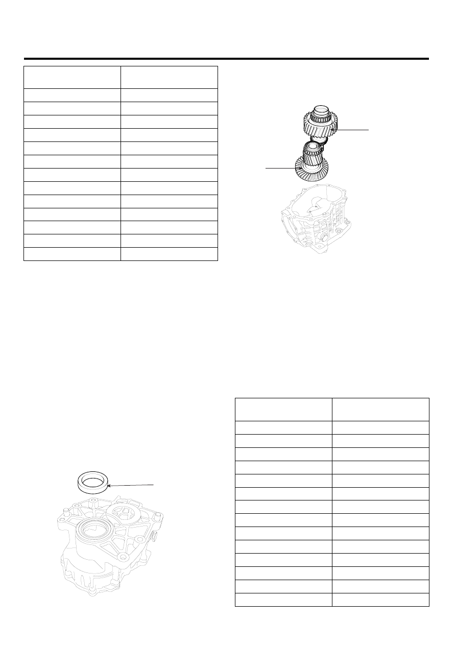
15. Install the hypoid gear shaft assembly(A) and the

transfer drive gear assembly(B) in the transfer hous-
ing.

A

B

SCMMT6072D

16. Measure the dimension F.

F. Assembled dimension of pinion assembly.
G
.

Finished dimension of transfer hous-

ing.(=88.0mm)
E
. Mounting distance(=69.500 ± deviation).

17. Select the spacer thickness from the chart below.

Thickness S1=E+F-G

NOTE

If it is not possible to reach the exact mounting dis-
tance, select the next thinner spacer S1.

PART NUMBER

SPACER

THICKNESS(mm)

47385-39125

1.25-1.28

47385-39129

1.29-1.32

47385-39133

1.33-1.36

47385-39137

1.37-1.40

47385-39141

1.41-1.44

47385-39145

1.45-1.48

47385-39149

1.49-1.52

47385-39153

1.53-1.56

47385-39157

1.57-1.60

47385-39161

1.61-1.64

47385-39165

1.65-1.68

47385-39169

1.69-1.72

47385-39172

1.720-1.739

47385-39174

1.740-1.759

TRANSFER CASE ASSEMBLY

MT -85

PART NUMBER

SPACER

THICKNESS(mm)

47385-39176

1.760-1.779

47385-39178

1.780-1.799

47385-39180

1.800-1.819

47385-39182

1.820-1.839

47385-39184

1.840-1.859

47385-39186

1.860-1.879

47385-39188

1.880-1.899

47385-39190

1.900-1.919

47385-39192

1.920-1.939

47385-39194

1.940-1.959

47385-39196

1.960-1.979

47385-39198

1.980-1.999

47385-39200

2.000-2.019

47385-39202

2.020-2.039

47385-39204

2.040-2.059

47385-39206

2.060-2.079

PART NUMBER

SPACER

THICKNESS(mm)

47385-39208

2.080-2.099

47385-39210

2.100-2.119

47385-39213

2.13-2.16

47385-39217

2.17-2.20

47385-39221

2.21-2.24

47385-39225

2.25-2.28

47385-39229

2.29-2.32

47385-39233

2.33-2.36

18. Install the pinion assembly with the selected spacer

above and measure the circumference backlash on
pinion.
(Measuring diameter, backlash and permissible devi-
ations for measurement on pinion, see table below).
If the result is out of permissible range, change the
spacer thickness S2, then start again with the step
8~12).

TIPS FOR SPACER ADJUSTMENT FOR HYPOID GEAR BACKLASH AND CONTACT PATTERN

ITEM

SYMPTOM

REMEDY

When more than the standard value
(0.16 ~ 0.21mm)

Adjust backlash by installing the spacer
S1 using a thinner one and gradually
installing a thicker one.

Backlash

When less than the standard value
(0.16 ~0.21mm)

Adjust backlash by installing the spacer
S1 using a thicker one and gradually
installing a thinner one.

ITEM

SYMPTOM

REMEDY

Drive

Coast

UMQG004D

• Normal state
• Standard tooth pattern

-

Both drive and coast surfaces are in
center in lateral direction and slightly
incline to TOE side in vertical direction

• If the pattern deviates from the standard,

adjust it by following procedure

Hypoid gear tooth
contacy pattern

Drive

Coast

UMQG004E

• Abnormal state
• The dirve surface inclines to TOE and

TOP and the coast surface inclines
to HEEL and TOP

The tooth contact pattern can be moved
to the arrow direction by installing the
spacer S2 using a thinner one and gradually
installing a thicker one.

MT -86

MANUAL TRANSAXLE (M5GF2)

19. Remove the pinion assembly. With the spacer S3

and transfer cover mounted, combined preload torque
for the hypoid gear shaft assembly and transfer gear
(measured on transfer gear) should be 2.7 to 3.8Nm.
The spacer S3 has to be changed, if the preload
torque is not within the permissible range.

20. Tighten the pinion assembly mounting bolts (B-7EA)

to install the pinion assembly(A).

TORQUE:
37~40 Nm(3.7~4.0 kgf.m, 14.5~21.7 lb-ft)

NOTE

1.

Before installing the pinion assembly, check the
pinion O-ring and apply the oil to the O-ring.

2.

To make the installation of the pinion to the trans-
fer easier, tap the pinion using a plastic hammer
after aligning the bolt holes.

A

B

SCMMT6070D

INSTALLATION

E5F331AD

[DIESEL 2.2L]

1.

Installation is in reverse order of removal.

CAUTION

Must use a new O-ring(47354-39300) which is
placed between the transaxle and the transfer
case.

2.

Remove the filler plug(A).

A

SCMMT6063D

3.

Refill the specification to the specified quantity.

Specification : API GL-5, SAE 75w/90
Quantity : Approx 0.8L

[GASOLINE 2.7L]

1.

Install the transfer assembly to the transaxle.

NOTE

To install the transfer easily, install it by moving the
pinion left and right directions, and slightly rotating the
inner drive shaft of transfer assembly.

2.

Install the transfer mounting bolts(4EA).

TORQUE:
62~67 Nm(6.2~6.7 kgf.m, 44.8~48.5 lb-ft)

3.

Install the transfer mounting bracket.

TORQUE:
47~51 Nm(4.7~5.1 kgf.m, 34.0~36.9 lb-ft) - 2EA
24~28 Nm(2.4~2.8 kgf.m, 17.4~20.3 lb-ft) - 2EA

TRANSFER CASE ASSEMBLY

MT -87

4.

Tighten the exhaust manifold mounting nuts(7EA).

TORQUE:
30~35 Nm(3.0~3.5 kgf.m, 21.7~25.3 lb-ft)

5.

Tighten the heat protector(A) mounting nuts(3EA).

TORQUE:
11.8~14.7 Nm(1.2~1.5 kgf.m, 8.7~10.8 lb-ft)

A

UMQG002K

6.

Tighten the pinion case mounting bolts(6EA).

TORQUE:
37~40 Nm(3.7~4.0 kgf.m, 14.5~21.7 lb-ft)

A

SCMMT6027L

7.

Refill the transfer oil through the filler plug.

8.

Install the front exhaust pipe assembly(A).

A

SCMMT6022L

9.

Install the drive shaft(RH) to the transfer assembly,
lower arm ball joint mounting and steering bar tie rod
ball joint.

10. Lower the vehicle down.

11. Install the engine side cover (RH) and the wheel and

tire(RH).

12. Install the oxygen sensor connector bracket and con-

nect the oxygen sensor connector(A,B). (Engine room
right side).

A

B

SCMMT6025L

13. Connect the battery negative (-) cable.


Content   ..  729  730  731  732   ..