Hyundai Santa Fe (2006 year). Manual - part 687


  Index      Hyundai     Hyundai Santa Fe - service repair manual 2006 year


Search            


Content   ..  685  686  687  688   ..


Hyundai Santa Fe (2006 year). Manual - part 687


HA -126

HEATING, VENTILATION AND AIR CONDITIONING

MONITOR SCANTOOL DATA

E2472961

1.

Connect scantool to data link connector(DLC).

2.

Engine "ON"

3.

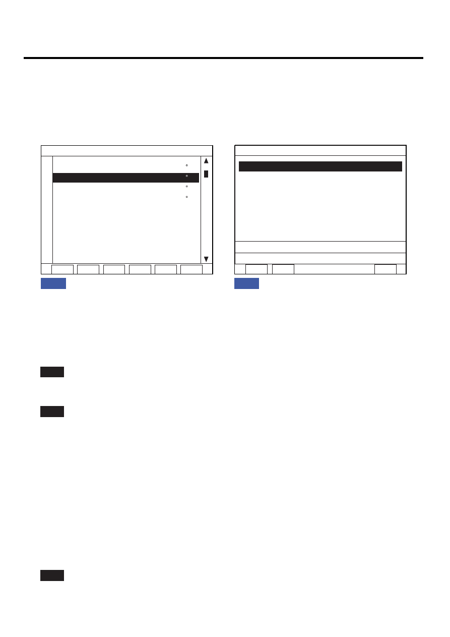
Monitor the "INCAR TEMP. SENSOR" Parameter on the Scantool.

1.2 CURRENT DATA

FIX

SCRN FULL

PART GRPH HELP

13.0  C

25.0  C

11.5  C

12.5  C

0.00 V

75.68 %

89.79 %

255

HEATER WATER TEMP. SNSR

IN-CAR TEMP. SENSOR

AMBIENT AIR TEMP. SNS

EVAPORATIVE SENSOR

DRIVER PHOTO SENSOR

AIR MIX POPENTIO. (DR.)

DIRECTION POTENIO. DR.

PASSENGER PHOTO SENSOR

1.1 DIAGNOSTIC TROUBLE CODES

NUMBER OF DTC : 1 ITEMS

PART

ERAS

HELP

B1233 IN-CAR TEMP. SNSR LOW

Fig 1 : The current data in abnormal state.
Fig 2 : DTC B1233.

Fig. 1

Fig. 2

EQBF514A

4.

Are the DTC B1233 present and is parameter of "INCAR TEMP. SENSOR" fixed?

Parameter of "INCAR TEMP. SENSOR" will be fixed at 25℃(77℉), if there is any fault in INCAR TEMP. SENSOR.

YES

Go to "Inspection" procedure.

NO

Fault is intermittent caused by poor contact in the sensor’s and/or A/C controller’s connector or was repaired and
A/C controller memory was not cleared. Thoroughly check connectors for looseness, poor connection, bending,
corrosion, contamination, deterioration, or damage. Repair or replace as necessary and then go to "Verification of
Vehicle Repair" procedure.

TERMINAL AND CONNECTOR INSPECTION

EB821E5B

1.

Many malfunctions in the electrical system are caused by poor harness and terminals.
Faults can also be caused by interference from other electrical systems, and mechanical or chemical damage.

2.

Thoroughly check connectors for looseness, poor connection, bending, corrosion, contamination, deterioration, or
damage.

3.

Has a problem been found?

YES

Repair as necessary and go to "Verification of Vehicle Repair" procedure.

BLOWER AND A/C CONTROLS (AUTOMATIC)

HA -127

NO

Go to "Signal circuit inspection" procedure.

SIGNAL CIRCUIT INSPECTION

EBF88FB5

1.

Check for short to ground in harness.

1) Ignition "OFF"

2) Disconnect incar sensor.

3) Measure resistance between terminal "4" of incar sensor and chassis ground.

Specification : Approx. ∞Ω

1

2

3

5 4

6

1. Motor(-)
2. Sensor ground
3. Humidity sensor signal

4. In-car sensor temp. signal

5. Sensor power (5V)
6. Motor(+)

SCMHA6529L

4) Is the measured resistance within specifications?

YES

Go to "Component Inspection" procedure.

NO

Check for short to ground in harness. Repair as necessary and go to "Verification of Vehicle Repair" procedure.

COMPONENT INSPECTION

E6BB9B31

1.

Check incar temp. sensor.

1) Ignition "OFF"

2) Disconnect incar sensor.

3) Measure resistance between terminal "4" and "2" of incar sensor.

Specification : Refer the specifications in fig 3.

HA -128

HEATING, VENTILATION AND AIR CONDITIONING

1

2

3

5 4

6

1. Motor(-)

2. Sensor ground

3. Humidity sensor signal

4. In-car sensor temp. signal

5. Sensor power (5V)
6. Motor(+)

SCMHA6530L

216.07

97.71

47.13

30.0

15.59

10.81

7.46

509.57

0

90

180

270

360

450

540

-30

-15

0

15

25

35

50

60

Resistance

Fig 3) Specifications : Resistance value of incar temp. sensor as a function of temperature.

Fig. 3

(k

Ω)

T emper atur e( c)

EQBF514G

4) Is the measured resistance within specifications in fig3? (tolerance limits ± 3%)

YES

Go to "Check A/C Control Unit" procedure.

NO

Substitute with a known-good incar sensor and check for proper operation.
If the problem is corrected, replace incar sensor and then go to "Verification of Vehicle Repair" procedure.

2.

Check A/C Control Unit

1) Engine "ON"

2) Disconnect incar sensor.

3) Measure Voltage between terminal "5" of A/C Control Unit and chassis ground.

Specification : Approx. 5V

BLOWER AND A/C CONTROLS (AUTOMATIC)

HA -129

5.  Incar sensor temp. signal

1

12

15

17

19

14 13

16

18

20

21

22

2

3

4

5

6

7

8

9

10

11

v

SCMHA6531L

4) Is the measured voltage within specifications?

YES

Check connectors for looseness, poor connection, bending, corrosion, contamination, deterioration, or damage.
Repair or replace as necessary and then go to "Verification of Vehicle Repair" procedure.

NO

Substitute with a known-good A/C Control Unit and check for proper operation.
If the problem is corrected, replace A/C Control Unit and then go to "Verification of Vehicle Repair" procedure.

VERIFICATION OF VEHICLE REPAIR

E5F6DCB4

After a repair, it is essential to verify that the fault has been corrected.

1.

Connect scantool and select "Diagnostic Trouble Codes(DTCs)" mode and then clear DTC.

2.

Operate the vehicle and monitor the DTC on the scantool.

3.

Are any DTCs present?

YES

Go to the applicable troubleshooting procedure.

NO

System is performing to specification at this time.


Content   ..  685  686  687  688   ..