Hyundai Santa Fe (2006 year). Manual - part 621


  Index      Hyundai     Hyundai Santa Fe - service repair manual 2006 year


Search            


Content   ..  619  620  621  622   ..


Hyundai Santa Fe (2006 year). Manual - part 621


FLA -550

FUEL SYSTEM

SCMF16159L

5)

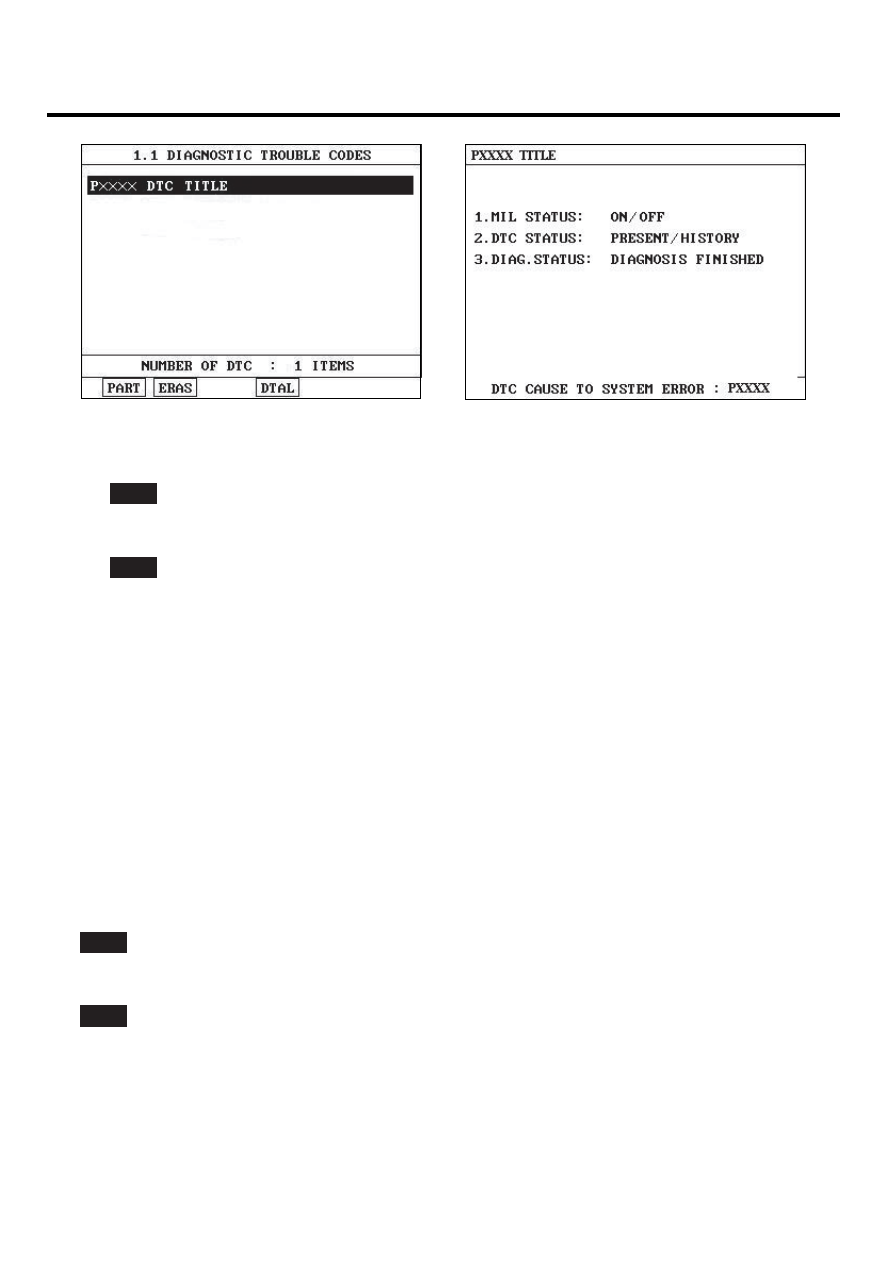
Is parameter displayed "Present fault"?

YES

▶ Go to "Terminal and connector inspection" procedure.

NO

▶ Fault is intermittent caused by poor contact in the sensor’s and/or PCM’s connector or was repaired and PCM
memory was not cleared. Thoroughly check connectors for looseness, poor connection, ending, corrosion, con-
tamination, deterioration, or damage. Repair or replace as necessary and go to "Verification of Vehicle Repair"
procedure.

VERIFICATION OF VEHICLE REPAIR

E003F048

After a repair, it is essential to verify that the fault has been corrected.

1.

Monitor and record the Freeze Frame Data for the Diagnostic Trouble Code(DTC) which has been diagnosed.

2.

Using a Scantool, Clear the DTCs

3.

Operate the vehicle within conditions noted in the freeze frame data or enable conditions

4.

Monitor that all rediness test have been verified as " Complete "

5.

Are any DTCs present ?

YES

▶ Go to the applicable troubleshoooting procedure.

NO

▶ System is performing to specification at this time.

DTC TROUBLESHOOTING PROCEDURES

FLA -551

DTC P1523 ETC (ELECTRONIC THROTTLE CONTROL) SYSTEM
MALFUNCTION - THROTTLE VALVE STUCK

COMPONENT LOCATION

EB59E45B

ETC Module (TPS + ETC Motor)

MAPS

SCMF16192L

GENERAL DESCRIPTION

EE5F5D1C

The Electronic Throttle Control(ETC) system is made of the components throttle body, Throttle Position Sensor(TPS)1&
2 and Accelerator Position Sensor(APS) 1&2. The throttle body contains the actuator, the throttle plate and the throttle
position sensor (potentiometer), which are integrated in one housing. The actuator consists of a DC motor with a two-stage
gear. The opening angle of the throttle valve is detected by the throttle position sensor which is mounted on the throttle
body. And it provides feedback to the ECM to control the throttle motor in order to control the throttle valve opening angle
properly in response to the driving condition.

DTC DESCRIPTION

EB974B1A

Checking throttle valve return state, under detecting condition, if an output signal is within the threshold value for more
than designated time, PCM sets P1523.

DTC DETECTING CONDITION

E50C17A4

Item

Detecting Condition

Possible cause

DTC Strategy

• This code detects when throttle fails to return

to the unpowered default position when power
to the ETC motor is turned off.

EnableConditions

• Throttle Actuation Mode Previous NOT Off
• Throttle Actuation Mode is Off
• ETC Power Control Mode = Normal
• TPS 1 & 2 = normal
• Sensor Supply voltage = Normal

Threshold value

• If throttle did not return to default range within

calculated seconds of turning off, increment fail count.

DiagnosisTime

• Continuous

MIL On Condition

• DTC only (NO MIL ON)

• Carbon in throttle
• Broken Throttle return spring
• throttle sticky
• throttle icy
• PCM

FLA -552

FUEL SYSTEM

SPECIFICATION

E619966F

Output voltage (V) [Vref = 5.0V]

Throttle opening (

)

TPS1

TPS2

0

0.0V

5.0V

10

0.5V

4.5V

20

0.9V

4.1V

30

1.4V

3.6V

40

1.8V

3.2V

50

2.3V

2.7V

60

2.7V

2.3V

70

3.2V

1.8V

80

3.6V

1.4V

90

4.1V

0.9V

100

4.5V

0.5V

110

5.0V

0.0V

DTC TROUBLESHOOTING PROCEDURES

FLA -553

SCHEMATIC DIAGRAM

ED82E1D0

[CIRCUIT DIAGRAM]

[HARNESS CONNECTORS]

[CONNECTION INFORMATION]

ETC MODULE

C86

Terminal

Connected to

Function

1

2

ETC Module (C86)

3

4

PCM C30-B  (16)

TPS 1 Reference Voltage (+5V)

5

6

PCM C30-B (57)

TPS 2 Signal

7

PCM C30-B  (48)

TPS 1 Signal

8

PCM C30-B  (14)

TPS 1 Ground

PCM (C30-B)

PCM

C30-B

1

2

5

6

3

4

7

8

PCM C30-B (2)

ETC Motor [+] Control

PCM C30-B  (58)

TPS 2 Ground

TPS 2 Reference Voltage (+5V)

PCM C30-B (13)

ETC Motor [-] Control

PCM C30-B (1)

1

21

2

22

3

23

4

24

5

25

6

26

7

27

8

28

9

29

10

30

11

31

12

32

13

33

14

34

15

35

16

36

17

37

18

38

19

39

20

40

41

61

42

62

43

63

44

64

45

65

46

66

47

67

48

68

49

69

50

70

51

71

52

72

53

73

54

74

55

75

56

76

57

77

58

78

59

79

60

80

1

2

4


TPS 1

TPS 2

ETC MOTOR

16 - Reference Voltage (+5V)

48 - TPS 1 Signal

14 - GND

6

3

7

13 - Reference Voltage (+5V)

57 - TPS 2 Signal

58 - GND

8

5

2 - ETC Motor [+] 

1 - ETC Motor [-]

M

SCMF16101L

SIGNAL WAVEFROM AND DATA

EE3582E5

Stepping on accelleraton pedal.

Pulling out accelleration cable with hand.

EGRF963A


Content   ..  619  620  621  622   ..