Hyundai Santa Fe (2006 year). Manual - part 622


  Index      Hyundai     Hyundai Santa Fe - service repair manual 2006 year


Search            


Content   ..  620  621  622  623   ..


Hyundai Santa Fe (2006 year). Manual - part 622


FLA -554

FUEL SYSTEM

MONITOR DTC STATUS

E4C7F759

1.

Check DTC Status

1)

Connect scantool to Data Link Connector(DLC).

2)

IG "ON".

3)

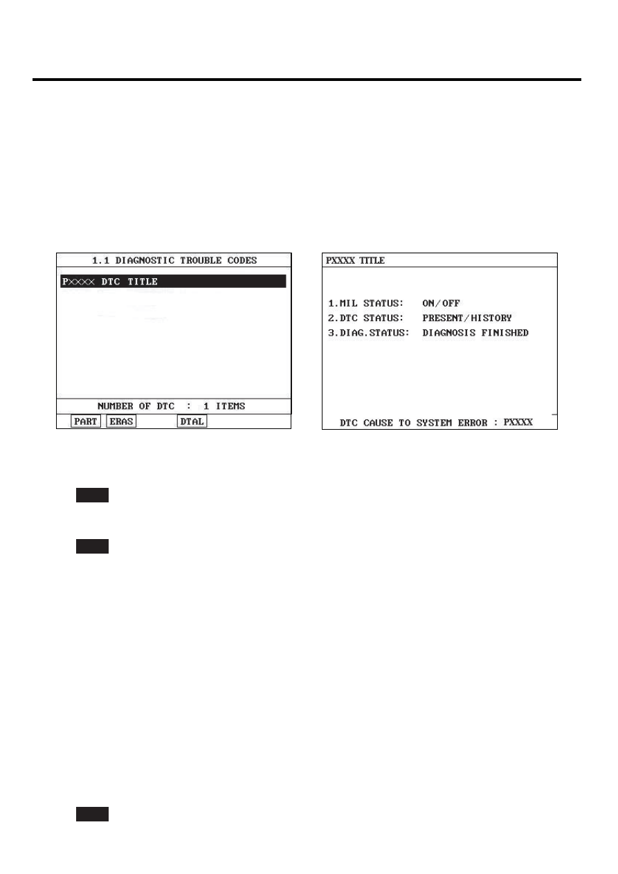
Select "Diagnostic Trouble Codes(DTCs)" mode, and then Press F4(DTAL) to check DTC’s information from the
DTCs menu

4)

Read "DTC Status" parameter.

SCMF16159L

5)

Is parameter displayed "Present fault"?

YES

▶ Go to "System Inspection" procedure.

NO

▶ Fault is intermittent caused by poor contact in the sensor’s and/or PCM’s connector or was repaired and PCM
memory was not cleared. Thoroughly check connectors for looseness, poor connection, ending, corrosion, con-
tamination, deterioration, or damage. Repair or replace as necessary and go to "Verification of Vehicle Repair"
procedure.

SYSTEM INSPECTION

E088FCD7

1.

Visual Inspection

1)

IG "OFF".

2)

Check throttle valve after removing air duct.
-

Carbon deposit.

-

Throttle icy

-

Broken return spring.

-

Throttle sticky

3)

Is the throttle valve return O.K ?

YES

DTC TROUBLESHOOTING PROCEDURES

FLA -555

▶Substitute with a known-good PCM and check for proper operation. If the problem is corrected,replace PCM
and then go to "Verification of Vehicle Repair" procedure.

NOTE

There is a memory reset function on scantool that can erase optional parts automaticallydetected and memorized by
PCM.
Before or after testing PCM on the vehicle, use this function to reuse the PCM on the others

NO

▶ Repair or replace as necessary and then, do ETS Initialization" as follows. then, go to "Verification of Vehicle
Repair" procedure.

※ Procedure of ETS Initialization
1. Erase the trouble codes on PCM
2. Turn the ignition key off and keep this condition until the main relay is turned off.(It will takes 10sec.)
3. Turn ignition key on more than 1second to record the throttle motor position on the EEPROM

VERIFICATION OF VEHICLE REPAIR

E5449986

After a repair, it is essential to verify that the fault has been corrected.

1.

Monitor and record the Freeze Frame Data for the Diagnostic Trouble Code(DTC) which has been diagnosed.

2.

Using a Scantool, Clear the DTCs

3.

Operate the vehicle within conditions noted in the freeze frame data or enable conditions

4.

Monitor that all rediness test have been verified as " Complete "

5.

Are any DTCs present ?

YES

▶ Go to the applicable troubleshoooting procedure.

NO

▶ System is performing to specification at this time.

FLA -556

FUEL SYSTEM

DTC P2104 ETC (ELECTRONIC THROTTLE CONTROL) SYSTEM
MALFUNCTION - FORCED IDLE

COMPONENT LOCATION

EAF6C0A5

ETC Module (TPS + ETC Motor)

MAPS

SCMF16192L

GENERAL DESCRIPTION

E672DD19

The Electronic Throttle Control(ETC) system is made of the components throttle body, Throttle Position Sensor(TPS)1&
2 and Accelerator Position Sensor(APS) 1&2. The throttle body contains the actuator, the throttle plate and the throttle
position sensor (potentiometer), which are integrated in one housing. The actuator consists of a DC motor with a two-stage
gear. The opening angle of the throttle valve is detected by the throttle position sensor which is mounted on the throttle
body. And it provides feedback to the ECM to control the throttle motor in order to control the throttle valve opening angle
properly in response to the driving condition.

DTC DESCRIPTION

E079537C

PCM recognizes vehicle state as forced idle under detecting condition, and sets P2104 and then MIL(Malfunction Indica-
tion Lamp) turns on.

DTC DETECTING CONDITION

EA11BB7A

Item

Detecting Condition

Possible cause

DTC Strategy

• This code detects if the system is in Forced Idle Mode

Enable Conditions

• Ignition "ON"

Threshold value

• Forced Idle Mode is active

DiagnosisTime

• -

MIL On Condition

• 1 Driving Cycle

• Faulty APS
• Faulty APS+Brake
• Faulty APS + Vehicle

speed sensor

• Faulty APS + Vehicle speed

sensor + Brake

• Faulty PCM

DTC TROUBLESHOOTING PROCEDURES

FLA -557

SCHEMATIC DIAGRAM

EEFB2F29

[CIRCUIT DIAGRAM]

[HARNESS CONNECTORS]

[CONNECTION INFORMATION]

ETC MODULE

C86

Terminal

Connected to

Function

1

2

ETC Module (C86)

3

4

PCM C30-B  (16)

TPS 1 Reference Voltage (+5V)

5

6

PCM C30-B (57)

TPS 2 Signal

7

PCM C30-B  (48)

TPS 1 Signal

8

PCM C30-B  (14)

TPS 1 Ground

PCM (C30-B)

PCM

C30-B

1

2

5

6

3

4

7

8

PCM C30-B (2)

ETC Motor [+] Control

PCM C30-B  (58)

TPS 2 Ground

TPS 2 Reference Voltage (+5V)

PCM C30-B (13)

ETC Motor [-] Control

PCM C30-B (1)

1

21

2

22

3

23

4

24

5

25

6

26

7

27

8

28

9

29

10

30

11

31

12

32

13

33

14

34

15

35

16

36

17

37

18

38

19

39

20

40

41

61

42

62

43

63

44

64

45

65

46

66

47

67

48

68

49

69

50

70

51

71

52

72

53

73

54

74

55

75

56

76

57

77

58

78

59

79

60

80

1

2

4


TPS 1

TPS 2

ETC MOTOR

16 - Reference Voltage (+5V)

48 - TPS 1 Signal

14 - GND

6

3

7

13 - Reference Voltage (+5V)

57 - TPS 2 Signal

58 - GND

8

5

2 - ETC Motor [+] 

1 - ETC Motor [-]

M

SCMF16101L

MONITOR SCANTOOL DATA

E02E6F62

1.

Connect scantool to DLC(Data Link Connector)

2.

IG "ON" & Monitor that any different DTC(Diagnostic Trouble Code) is existed.
(There will be at least one more DTC which causes this DTC P2104 to retrieve )

3.

Repair the DTCs cause DTC P2104 first according to the designated trouble shooting guide.
(After repairing the DTCs cause DTC P2104 , don’t forget to do "ETC Initialization" as follows.

4.

Is the same DTC occurred ?

YES

▶Substitute with a known-good PCM and check for proper operation. If the problem is corrected,replace PCM and
then go to "Verification of Vehicle Repair" procedure.


Content   ..  620  621  622  623   ..