Hyundai Santa Fe (2006 year). Manual - part 611
FLA -510
FUEL SYSTEM
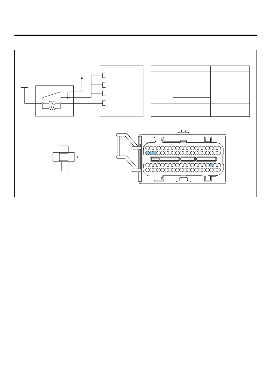
SCHEMATIC DIAGRAM
EDE659D9
4
PCM C30-A (43)
5
Main Relay
PCM
1
2
Battery
Power Supply (B+)
Battery Power (B+)
IGN COIL 20A
3
Power Supply (B+)
Main Relay Control
Battery
Battery Power (B+)
PCM C30-A (38)
PCM C30-A (39)
PCM C30-A (40)
PCM (C30-A)
1
3
2
4
5
C30-A
[CIRCUIT DIAGRAM]
[HARNESS CONNECTOR]
Terminal
Connected to
Function
3 2 1
6 5 4
9
21
23
16 15
17
18
19
38 37 36 35 34
39
40
26 25 24
22
27
28
29
46
47
48
49
68 67
69
70
42 41
43
44
62 61
63
64
66 65
45
56
57
58
59
60
78 77 76 75 74
79
80
52 51 50
53
72 71
73
54
55
32 31 30
33
20
14 13 12 11 10
8 7
[CONNECTION INFORMATION]
5
2
3
1
4
Battery
Main Relay
43 - Main Relay Control
40 - Power Supply (B+)
38 - Power Supply (B+)
39 - Power Supply (B+)
To IGN
COIL 20A
SCMF16377L
MONITOR DTC STATUS
EFABA80E
1.
Check DTC Status
1)
Connect scantool to Data Link Connector(DLC).
2)
IG "ON".
3)
Select "Diagnostic Trouble Codes(DTCs)" mode, and then Press F4(DTAL) to check DTC’s information from the
DTCs menu
4)
Read "DTC Status" parameter.