Hyundai Santa Fe (2006 year). Manual - part 588


  Index      Hyundai     Hyundai Santa Fe - service repair manual 2006 year


Search            


Content   ..  586  587  588  589   ..


Hyundai Santa Fe (2006 year). Manual - part 588


FLA -418

FUEL SYSTEM

SIGNAL CIRCUIT INSPECTION

1.

Check voltage from sensor side

1)

IG "OFF"

2)

Disconnect vehicle speed sensor connector.

3)

IG "ON" and ENG "OFF"

4)

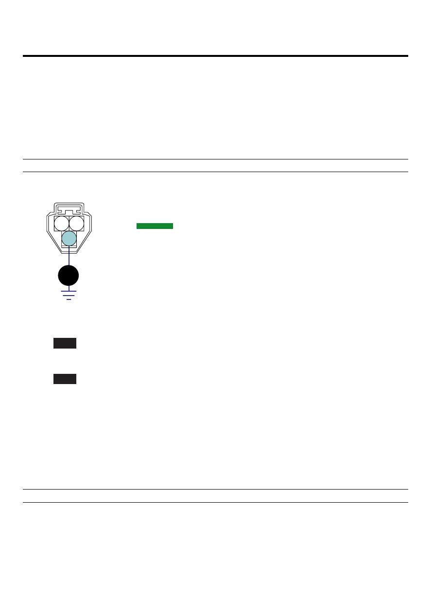
Measure voltage between terminal 3 of vehicle speed sensor harness connector and chassis ground.

Specification : Approx. 8 ~ 11.5V

v

1. VSS power
2. VSS ground

3

1

2

M/T:C246

A/T:C270

SCMF16362L

5)

Is the measured voltage within specifications?

YES

▶ Go to "Check voltage from PCM side" as follows.

NO

▶ Repair open or short to ground in harness, and go to "Verification of Vehicle Repair" procedure.

2.

Check voltage from PCM side

1)

IG "OFF"

2)

Disconnect PCM connector and vehicle speed sensor connector.

3)

IG "ON" and ENG "OFF"

4)

Measure voltage between terminal C30-A (52) of PCM harness connector and chassis ground.

Specification : Approx. 8 ~ 11.5V

DTC TROUBLESHOOTING PROCEDURES

FLA -419

3 2 1

6 5 4

9

21

22

24 23

16 15

17

18

38 37

39

40

26 25

27

28

29

30

31

46

47

48

49

68 67

65

69

70

42 41

43

44

62 61

63

64

66

45

56

57

58

59

60

78 77 76 75 74

79

80

51 50

53

72 71

73

54

55

32

33

34

35

36

20 19

14 13 12 11 10

8 7

52. Wheel speed sensor output(FR)

C30-A

v

52

SCMF16363L

5)

Is the measured voltage within specifications?

YES

▶ Go to " Ground circuit inspection " procedure.

NO

▶ Check open in harenss.
▶ Repair or replace as necessary and then, go to " Verification of Vehicle Repair" procedure.

GROUND CIRCUIT INSPECTION

1.

IG "OFF"

2.

Disconnect vehicle speed sensor connector.

3.

IG "ON" and ENG "OFF"

4.

Measure voltage between terminal 1 of vehicle speed sensor harness connector and chassis ground.(Fig.A)

5.

Measure voltage between terminals 1 and 2 of vehicle speed sensor harness connector.(Fig.B)

Specification : Measurement "A" - Measurement ’B’ = Approx. below 200mV

v

3. VSS signal

v

3

1

2

3

1

2

M/T:C246

A/T:C270

M/T:C246

A/T:C270

SCMF16364L

FLA -420

FUEL SYSTEM

6.

Is the measured voltage within specifications?

YES

▶ Substitute with a known - good vehicle speed sensor and check for proper operation. If the problem is not cor-
rectd, substitute with a known - good PCM and check for proper operation. And go to "Verification of Vehicle Repair"
procedure.

NO

▶ Repair open or contact resistance in harness, and go to "Verification of Vehicle Repair" procedure.

NOTE

There is a memory reset function on scantool that can erase optional parts automatically detected and memorized
by PCM. After testing PCM on the vehicle, use this function to reuse the PCM on the others

VERIFICATION OF VEHICLE REPAIR

EEFA2461

After a repair, it is essential to verify that the fault has been corrected.

1.

Monitor and record the Freeze Frame Data for the Diagnostic Trouble Code(DTC) which has been diagnosed.

2.

Using a Scantool, Clear the DTCs

3.

Operate the vehicle within conditions noted in the freeze frame data or enable conditions

4.

Monitor that all rediness test have been verified as " Complete "

5.

Are any DTCs present ?

YES

▶ Go to the applicable troubleshoooting procedure.

NO

▶ System is performing to specification at this time.

DTC TROUBLESHOOTING PROCEDURES

FLA -421

DTC P0504 BRAKE SWITCH "A"/"B" CORRELATION

GENERAL DESCRIPTION

EB611534

The Stop lamp switch is used to judge whether the acceleration system is abnormal or not. The stop lamp switch has a
duplex system(signals brake test or brake light) to memorize the abnormality when the signals of depressing and releasing
the brake pedal are detected simultaneously.

DTC DESCRIPTION

E8706E64

Checking output signals from both brake switch. when all of them are On or OFF simultaneously, if abnormal signal is
detected for more than 0.5 sec., an error is recognized. And if this condition lasts for certain period, PCM sets P0504.
MIL(Malfunction Indication Lamp) turns on when the malfunction lasts till cosecutive 2 driving cycle.

DTC DETECTING CONDITION

E1833C1F

Item

Detecting Condition

Possible cause

DTC Strategy

• Comparing 2 brake signals during driving

Case 1

• Engine works
• Vehicle Speed Sensor is abnormal.

Enable

Condi-

tions

Case 2

• Engine works
• Vehicle Speed Sensor is normal and Vehicle Speed

is over 20kph during 1sec or more.

Threshold value

• The one brake signal’s change duration when

another signal has been changed 〉0.5 sec

Diagnosis Time

• Continuous

MIL On Condition

• 2 driving cycles

• Poor connection
• Open or Short
• Faulty PCM

SPECIFICATION

E1C5364F

Item

During taking off the brake

During stepping on the brake

Brake Lamp Switch

0V

Battery voltage

Brake Switch

Battery voltage

0V


Content   ..  586  587  588  589   ..