Hyundai Santa Fe (2006 year). Manual - part 511
FLA -110
FUEL SYSTEM
DTC P0030 HO2S HEATER CONTROL CIRCUIT (BANK 1 / SENSOR 1)
COMPONENT LOCATION
ECC4F0DF
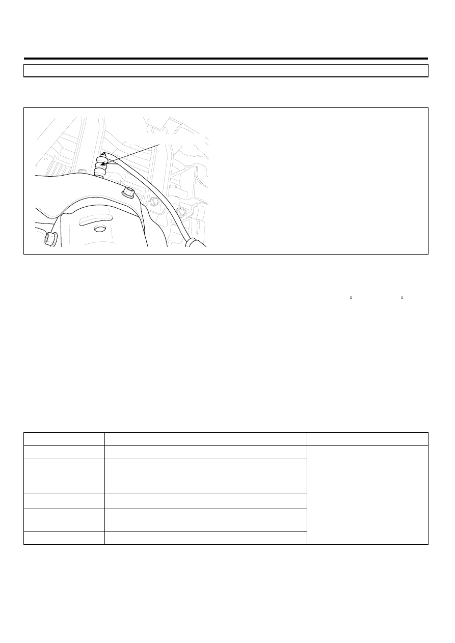
HO2S [Bank 1/Sensor 1]
LGLG504A
GENERAL DESCRIPTION
E7D9053E
The normal operating temperature of the HO2S(Heated Oxygen Sensor) ranges from 350 to 850 C(662 to 1562 F). The
HO2S heater greatly decreases the amount of time required for fuel control to become active. The ECM provides a pulse
width modulated control circuit to adjust current through the heater. When the HO2S is cold, the value of the resistance is
low and the current in the circuit is high. On the contrary, if the temperature in the resistor of the sensor rises, the current
drops gradually.
DTC DESCRIPTION
E55501AD
Checking current from HO2S under detecting condition,if the heater current is below a certain threshold for more than
predeterminate time, PCM sets P0030. MIL(Malfunction Indication Lamp) turns on when the malfunction lasts till consec-
utive 2 driving cycle.
DTC DETECTING CONDITION
E1805512
Item
Detecting Condition
Possible cause
DTC Strategy
• Monitor the current through the heater
Enable Conditions
• Engine Running > 60 sec.
• Heater Duty Cycle > 40%
• Max. Duty Cycle - Min. Duty Cycle < 5%
Threshold value
• Filtered Heater Current < threshold value
Diagnosis Time
• Continuous
(More than 2.5 second failure for every 5 second test )
MIL On Condition
• 2 Driving Cycles
• Poor Connection
• Contact Resistance
• HO2S(B1/S1)
• PCM