Hyundai Santa Fe (2006 year). Manual - part 476
 

  Index      Hyundai     Hyundai Santa Fe - service repair manual 2006 year


Search            


Content   ..  474  475  476  477   ..


Hyundai Santa Fe (2006 year). Manual - part 476


FL -514

FUEL SYSTEM

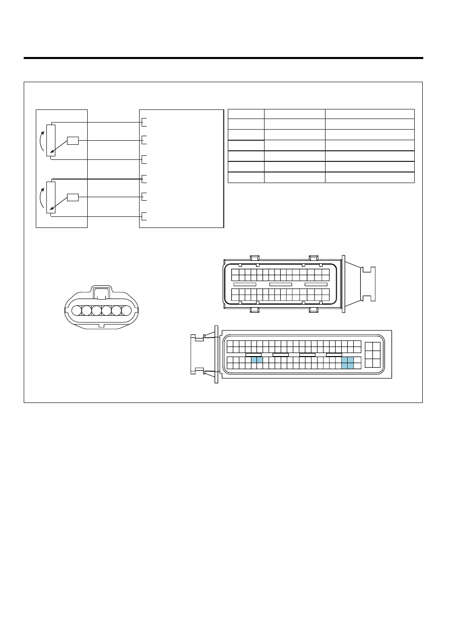
SCHEMATIC DIAGRAM

EFFA706D

APS

C256

1

2

ECM C230-K (9)

APS 1 Signal

3

4

ECM C230-K (45)

APS 2 Reference Voltage (+5V)

APS 2 Ground

5

ECM C230-K (30)

APS 1 Ground

6

ECM C230-K (8)

APS 1 Reference Voltage (+5V)

ECM C230-K (31)

ECM (C230-K)

[CIRCUIT DIAGRAM]

[HARNESS CONNECTORS]

[CONNECTION INFORMATION]

Terminal

Connected to

Function

APS 2 Signal

ECM C230-K (46)

ECM

C230-A

C230-K

1

2

4

3

6

5

8 7

12

13

16

17

18

23 22

20

21

19

27 26 25 24

28

29

30

14

9

10

11

15

33 32 31

34

37

41

42

40 39 38

35

36

43

44

47 46

49 48

50

53

56

58 57

54

51

52

55

59

60
45

1

30 29

31

32

38

39

36

37

35

33

34

40

42 41

46 45 44 43

48 47

50 49

2

3

4

6

5

8

7

12 11 10 9

13

14

15

18 17

19

16

22

25

27 26

23

20

21

24

28

51

75 74
53 52

73

79 78 77 76

80

81

83 82

84

86 85

87

89 88

90

92 91

93

94

57

69 68

70

71

64

54

55

56

61

58

59

60

63 62

65

66

67

72

1

2

3

4

5

6

5

2

4

APS (C256)

APS 1

APS 2

45 - Reference Voltage (+5V)

9 - APS 1 Signal

30 - GND

6

3

1

46 - Reference Voltage (+5V)

31 - APS 2 Signal

8 - GND

SCMFL6123L

DTC TROUBLESHOOTING PROCEDURES

FL -515

SIGNAL WAVEFORM AND DATA

E4BA1C5F

Fig.1

Fig.1) APS 1 and APS 2 signals are measured simultaneously,  Check if output value is rising and APS 2 is 1/2 of APS 1 signal. 

APS 2 ground check
signal

APS 1

APS 2

LFIG541A

NOTE

APS 2 Ground checking signal is for ECM to monitor APS 2. This signal drops APS 2 output voltage to below
200.39mV per 200msec. If APS 2 output voltage does not drop to below 200.39mV, ECM sets DTC as recognizing
ground circuit error of APS 2 .

The waveform below 200.39mV is not detectable in Ground checking signal waveform of APS 2 signal. Instead, the

waveform which drops a little is detected. If APS 2 data of "SERVICE DATA" on the Scantool varies from 350mV to 0mV
periodically, it means it works well.

MONITOR SCANTOOL DATA

E548F419

1.

Connect Scantool to Data Link Connector (DLC).

2.

Warm engine up to normal operating temperature.

3.

Turn "OFF" electrical devices and A/C.

4.

Monitor "Accelerator position sensor", "Accelerator position sensor 1", "Accelerator position sensor 2 " parameter on
the scantool.

Specification : at idle( 0% ) Accelerator position sensor 1 : 600mV~800mV
Accelerator position sensor 2 : 1/2 of Accelerator position sensor 1

FL -516

FUEL SYSTEM

Fig.1

Fig.1) APS output data at warm idle. Check if output value is rising and "Accelerator position sensor 2" is 1/2 of 
          "Accelerator position sensor 1" signal.

SCMFL6371L

TERMINAL AND CONNECTOR INSPECTION

E166C946

1.

Electrical systems consist of a lot of harness and connectors, poor connection of terminals can cause various prob-
lems and damge of component.

2.

Perform checking procedure as follows.

1)

Check damage of harness and terminals : Check terminals for contact resistance, corrosion and deformation.

2)

Check connecting condition of ECM and component connector : Check terminal seperation, damage of locking
device and connecting condition between terminal and wiring.

NOTE

Disconnect the pin which requires checking at male connector and insert it to the terminal at female connector for
checking connecting condition. ( after checking, reconnect the pin at correct position. )

3.

Is the problem found?

YES

Repair the trouble causing part and go to "Verification of Vehicle Repair".

NO

Go to "Power Circuit Inspection" as follows.

POWER CIRCUIT INSPECTION

EF179E48

1.

IG KEY "OFF", ENGINE "OFF"

2.

Disconnect APS connector.

3.

IG KEY "ON"

4.

Measure the voltage of terminal 1 and 4 of APS connector.

Specification : 4.8V~5.1V

DTC TROUBLESHOOTING PROCEDURES

FL -517

5.

Is the measured voltage within the specification?

YES

Go to "Signal Circuit Inspection".

NO

If the measured voltage is not within the specified value, find and repair trouble causing part in circuits and go to

"Verification of Vehicle Repair".
When the measured voltage is higher than the specified value :
Refer to P0643 Circuit Inspection. (APS1)
Refer to P0653 Circuit Inspection.(APS2)
When the measured voltage is lower than the specified value :
Refer to P0642 Circuit Inspection.(APS1)
Refer to P0652 Circuit Inspection.(APS2)

SIGNAL CIRCUIT INSPECTION

EC930780

1.

Check open in signal circuit

1)

IG KEY "OFF", ENGINE "OFF"

2)

Disconnect APS connector and ECM connector.

3)

Check continuity between APS connector terminal 2 and ECM connector (C230-K) terminal 9. ( APS 1)
Check continuity between APS connector terminal 3 and ECM connector (C230-K) terminal 31. ( APS 2)

Specification : Continuity (below 1.0

)

4)

Is the measured resistance within the specification?

YES

Go to "Check short in signal circuit".

NO

Repair open in signal circuit and go to "Verification of Vehicle Repair".

2.

Check short in signal circuit ( APS 1 )

1)

IG KEY "OFF", ENGINE "OFF"

2)

Disconnect APS connector and ECM connector.

3)

IG KEY "ON"

4)

Check continuity between APS connector terminal 2 and chassis ground. (check short to ground )
Measure the voltage of terminal 2 of APS connector. ( check short to battery )

Specification : Check short to ground : Discontinuity ( Infinite

)

Check short to battery : 0.0V~0.1V

5)

Is APS 1 signal circuit insulated normally?

YES


Content   ..  474  475  476  477   ..