Hyundai Santa Fe (2006 year). Manual - part 461
FL -454
FUEL SYSTEM
SIGNAL WAVEFORM AND DATA
E5AED65D
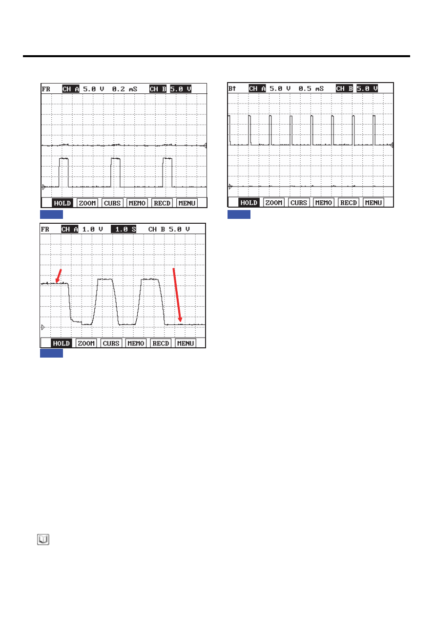
Fig.1
Fig.2
Fig.1) Waveform when variable swirl valve closed at idle. Terminal 1 is (+) and 2 is (-).
Fig. 2) Waveform when variable swirl valve opened at above 3000RPM. Terminal 1 is (-) and 2 is (+).
Fig. 3) Waveform of variable swirl control actuator motor position sensor at the point of turning engine OFF.
4.3V at swirl valve closed and 0.3V at swirl valve opened. Swirl valve is opened and closed twice at engine "OFF".
(Measured at terminal 4)
Fig.3
Swirl valve fully closed
Swirl valve fully opened
SCMFL6421L
TERMINAL AND CONNECTOR INSPECTION
E41E065B
1.
Electrical systems consist of a lot of harness and connectors, poor connection of terminals can cause various prob-
lems and damge of component.
2.
Perform checking procedure as follows.
1)
Check damage of harness and terminals : Check terminals for contact resistance, corrosion and deformation.
2)
Check connecting condition of ECM and component connector : Check terminal seperation, damage of locking
device and connecting condition between terminal and wiring.
NOTE
Disconnect the pin which requires checking at male connector and insert it to the terminal at female connector for
checking connecting condition. ( after checking, reconnect the pin at correct position. )
3.
Is the problem found?