Hyundai Santa Fe (2006 year). Manual - part 460


  Index      Hyundai     Hyundai Santa Fe - service repair manual 2006 year


Search            


Content   ..  458  459  460  461   ..


Hyundai Santa Fe (2006 year). Manual - part 460


FL -450

FUEL SYSTEM

LFIG504A

4)

Are both data identical?

YES

Go to "Verification of Vehicle Repair".

NO

If error is not corrected after reperforming "INJECTOR CORRECTION" procedure, replace ECM.

NOTE

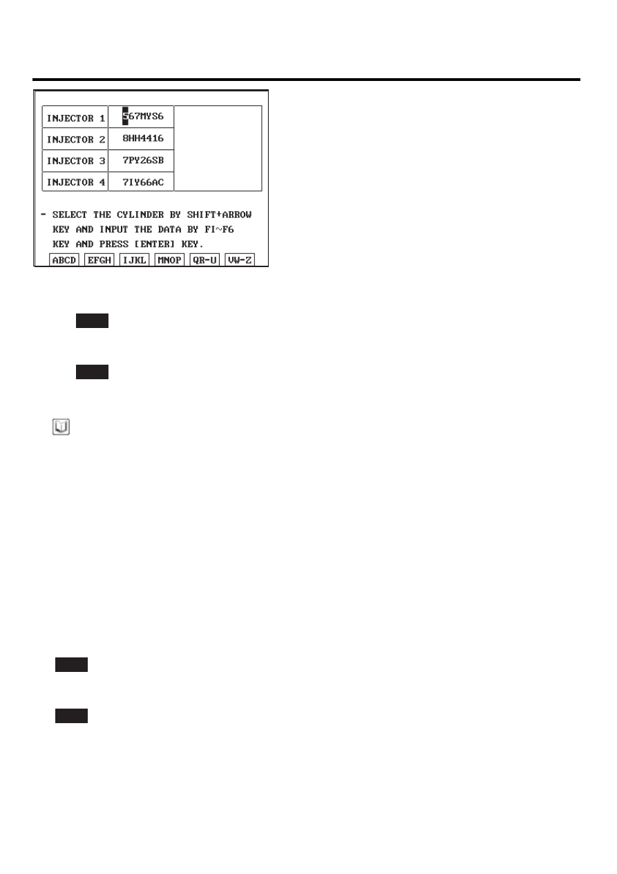
Input IQA data of injector mounted at cylinder at replacing ECM using scantool.
If this process is not performed, engine check lamp on cluster blinks and normal engine power generation is impos-
sible.

VERIFICATION OF VEHICLE REPAIR

EF565CD3

After a repair, it is essential to verify that the fault is corrected.

1.

After connecting Scantool select "DIAGNOSTIC TROUBLE CODES(DTCs)" mode.

2.

Clear recorded DTC using Scantool.

3.

Drive the vehicle within DTC "Enable conditions" in "General information".

4.

After selecting "DIAGNOSTIC TROUBLE CODES(DTCs)" mode and check if DTC is recorded again.

5.

Are any DTCs recorded ?

YES

Go to the DTC guide of recorded NO. in Scantool.

NO

System operates within specification.

DTC TROUBLESHOOTING PROCEDURES

FL -451

DTC P2009 INTAKE MANIFOLD RUNNER CONTROL CIRCUIT LOW(BANK 1)

COMPONENT LOCATION

EFE7A7B3

Variable Swirl Control Actuater

SCMFL6509L

GENERAL DESCRIPTION

E6F57131

Variable swirl control actuator consists of DC motor and motor position sensor(potentiometer) which detects the position
of swirl valve.As closing one intake port out of two at idle and below 3000RPM, swirl effect is taken on intake air. This
swirl effect increases air flow rate.

However, because air flow rate is too high, swirl effect is neglectable thus, swirl valve is opened for efficiency of intake air.

To prevent swirl valve and shaft form being stuck by foreign metarial, and to learn max opening and closing position of
swirl valve, it is fully opened and closed twice at turning engine OFF.

Swirl

The air flow which indicates Intake air swirls with respect to the axis passing through the centre of piston with length-
direction by intake port which is eccentric from the centre of combustion chamber.

DTC DESCRIPTION

E52AFD3E

P2009 is set when 1) short to ground in variable swirl actuator driving motor (+) or (-) output terminal. or 2) tiny open in
motor (-) output terminal for a long period occurs.The polarity of (+) and (-) lines shift each other in accordance with the
condition of swirl valve(opened or closed) thus, checking both (+) and (-) circuits is required.

FL -452

FUEL SYSTEM

DTC DETECTING CONDITION

E37B62CE

Item

Detecting Condition

Possible Cause

DTC Strategy

• Voltage monitoring

Enable Conditions

• IG KEY "ON"

Threshold Value

• Short to ground in motor output terminal - 0.2 sec.
• Tiny open in motor circuit - 0.3 sec.

Diagnostic Time

• Refer to Threshold value

Fuel cut

NO

EGR Off

NO

Fuel Limit

NO

Fail Safe

Check

Lamp

NO

• Swirl valve opened at variable

swirl control actuator failure

• Variable swirl valve motor

circuit

SPECIFICATION

E045EB87

Variable swirl control actuator characteristic curve

Degree

[ ]

Duty [%]

LFIG510A

DTC TROUBLESHOOTING PROCEDURES

FL -453

SCHEMATIC DIAGRAM

E70B0D6D

[CIRCUIT DIAGRAM]

[HARNESS CONNECTORS]

[CONNECTION INFORMATION]

VARIABLE SWIRL CONTROL ACTUATOR

C269

Terminal

Connected to

Function

VARIABLE SWIRL
CONTROL ACTUATOR (C269)

3

2

ECM C230-A (30)

Reference Voltage (+5V)

Motor [-] Control

1

ECM C230-A (60)

Motor [+] Control

ECM C230-A (26)

ECM (C230-A)

ECM

C230-A

C230-K

1

2

4

3

6

5

8 7

12

13

16

17

18

23 22

20

21

19

27 26 25 24

28

29

30

14

9

10

11

15

33 32 31

34

37

41

42

40 39 38

35

36

43

44

47 46

49 48

50

53

56

58 57

54

51

52

55

59

60
45

1

30 29

31

32

38

39

36

37

35

33

34

40

42 41

46 45 44 43

48 47

50 49

2

3

4

6

5

8

7

12 11 10 9

13

14

15

18 17

19

16

22

25

27 26

23

20

21

24

28

51

75 74
53 52

73

79 78 77 76

80

81

83 82

84

86 85

87

89 88

90

92 91

93

94

57

69 68

70

71

64

54

55

56

61

58

59

60

63 62

65

66

67

72

5

Sensor Ground

ECM C230-A (6)

4

ECM C230-A (56)

Position Signal

1

2

3

4

5

5

4

3


SENSOR

MOTOR

26 - Reference Voltage (+5V)

56 - Position Sensor Signal

6 - GND

1

2

30 - Motor [-] Control

60 - Motor [+] Control

M

SCMFL6132L


Content   ..  458  459  460  461   ..