Hyundai Santa Fe (2006 year). Manual - part 445
FL -390
FUEL SYSTEM
[CIRCUIT DIAGRAM]
[HARNESS CONNECTORS]
[CONNECTION INFORMATION]
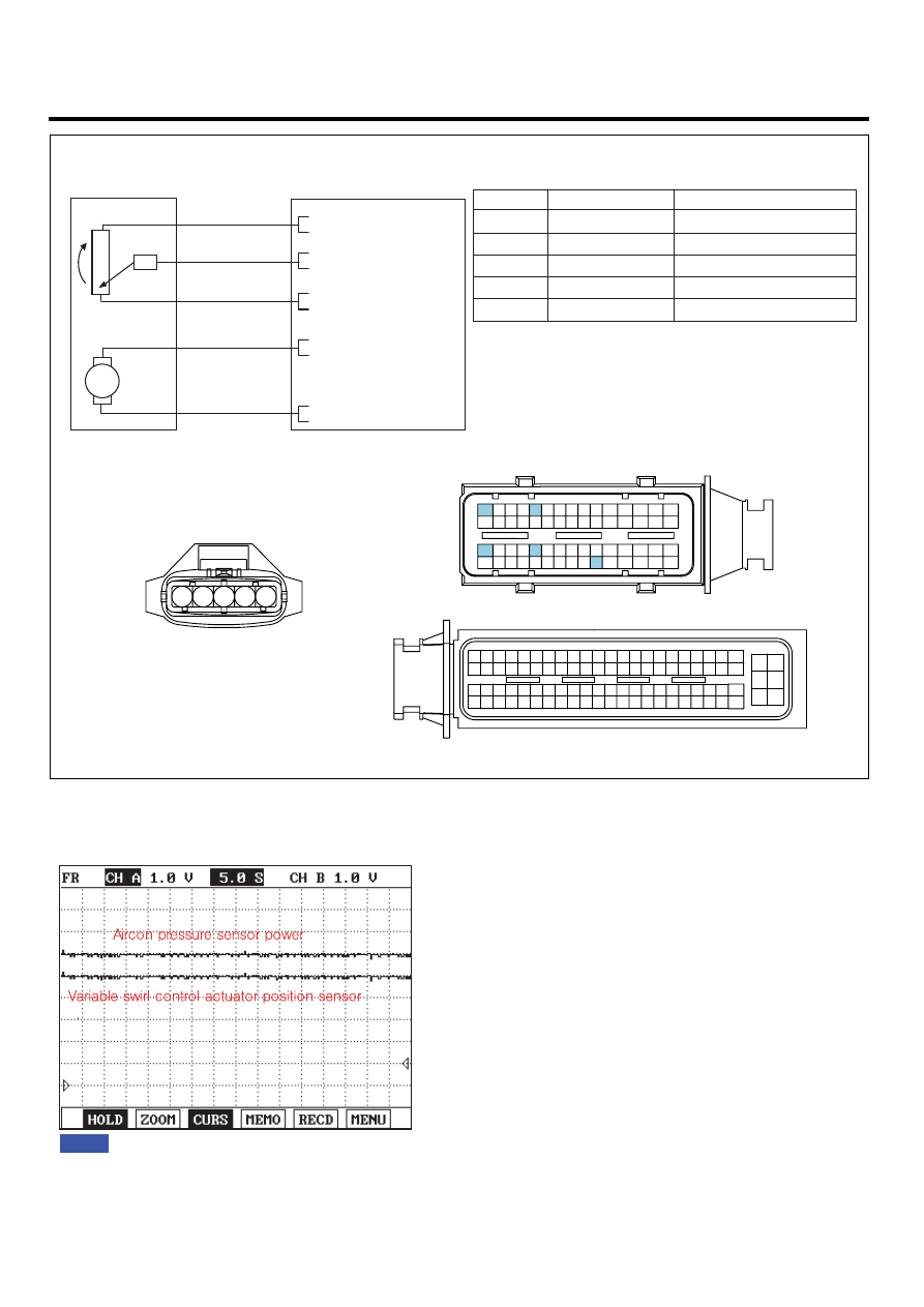
VARIABLE SWIRL CONTROL ACTUATOR
C269
Terminal
Connected to
Function
VARIABLE SWIRL
CONTROL ACTUATOR (C269)
3
2
ECM C230-A (30)
Reference Voltage (+5V)
Motor [-] Control
1
ECM C230-A (60)
Motor [+] Control
ECM C230-A (26)
ECM (C230-A)
ECM
C230-A
C230-K
1
2
4
3
6
5
8 7
12
13
16
17
18
23 22
20
21
19
27 26 25 24
28
29
30
14
9
10
11
15
33 32 31
34
37
41
42
40 39 38
35
36
43
44
47 46
49 48
50
53
56
58 57
54
51
52
55
59
60
45
1
30 29
31
32
38
39
36
37
35
33
34
40
42 41
46 45 44 43
48 47
50 49
2
3
4
6
5
8
7
12 11 10 9
13
14
15
18 17
19
16
22
25
27 26
23
20
21
24
28
51
75 74
53 52
73
79 78 77 76
80
81
83 82
84
86 85
87
89 88
90
92 91
93
94
57
69 68
70
71
64
54
55
56
61
58
59
60
63 62
65
66
67
72
5
Sensor Ground
ECM C230-A (6)
4
ECM C230-A (56)
Position Signal
1
2
3
4
5
5
4
3
SENSOR
MOTOR
26 - Reference Voltage (+5V)
56 - Position Sensor Signal
6 - GND
1
2
30 - Motor [-] Control
60 - Motor [+] Control
M
SCMFL6132L
SIGNAL WAVEFORM AND DATA
E2B9B3AE
Fig.1
Fig.1) A/C pressure transducer and VSA position Sensor power supply signals are measured simultaneously.
Check if the voltages are within the specification ( 4.8~5.1V) at IG KEY "ON"
LFIG455A