Hyundai Santa Fe (2006 year). Manual - part 446
FL -394
FUEL SYSTEM
DTC P0699 SENSOR REFERENCE VOLTAGE "C" CIRCUIT HIGH
GENERAL DESCRIPTION
E6EB821A
Refer to DTC P0698.
DTC DESCRIPTION
E8533693
P0699 is set when the voltage above 5.158V - maximum voltage of sensor power supply 3 generates from ECM - is
detected for more than 0.1 sec.. This code is due to the short to battery in sensor power circuit or the voltage problem
inside of ECM.
DTC DETECTING CONDITION
E7645EBA
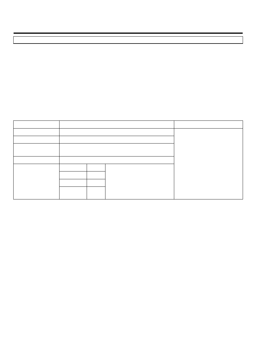
Item
Detecting Condition
Possible Cause
DTC Strategy
• Voltage monitoring
Enable Conditions
• IG KEY "ON"
Threshold Value
• when the voltage is above the maximum voltage
of sensor power supply(above 5.158V )
Diagnostic Time
• 0.1 sec.
Fuel cut
NO
EGR Off
NO
Fuel Limit
YES
Fail Safe
Check
Lamp
NO
• A/C pressure transducer
power supply circuit
• variable swirl control actuator
power supply circuit
• ECM component
SPECIFICATION
E1291B6F
Refer to DTC P0698.
SCHEMATIC DIAGRAM
EA7E13E7
Refer to DTC P0698.
SIGNAL WAVEFORM AND DATA
E71B02FB
Refer to DTC P0698.
TERMINAL AND CONNECTOR INSPECTION
ED0D429C
Refer to DTC P0698.
POWER CIRCUIT INSPECTION
E0F941F7
1.
Check power circuit voltage
1)
IG KEY "OFF", ENGINE "OFF"
2)
Disconnect A/C pressure transducer connector and variable swirl control actuator connector.