Hyundai Santa Fe (2006 year). Manual - part 340
CYLINDER HEAD ASSEMBLY
EMA -71
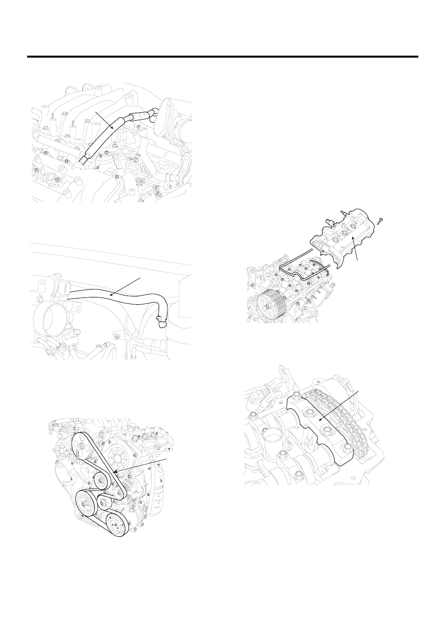
7.
Remove the PCV(Pulge Control Valve) hose(A).
A
KCBF180A
8.
Disconnect the brake vaccume hose(A).
A
LDLG036A
9.
Remove the heater hoses.
10. Remove the drive belt(A).
A
KCBF105A
11. Remove the power steering pump.(Refer to ’ST’
group).
12. Remove the exhaust manifold assembly.(Refer to ’In-
take and exhause system’).
13. Remove the intake manifold assembly.(Refer to ’In-
take and exhause system’).
14. Remove the timing belt.(Refer to ’Timing system’).
15. Remove the ignition coils.
16. Remove the water temp. control assembly.
17. Remove the cylinder head cover(A).
A
KCBF177A
18. Remove the camshaft bearing cap(A).
A
KCBF167A