Hyundai Santa Fe (2006 year). Manual - part 283
GENERAL
EE -11
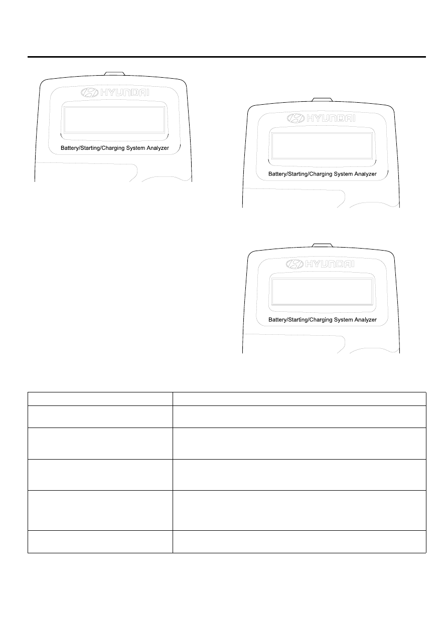
TURN LOADS ON
ENTER TO CONT...
SCMEE6113L
NOTE
When asked to turn on the accessory loads, turn on
the blower to high(heater), the high beam headlights,
and rear defogger. DO NOT use cyclical loads such
as air conditioning or wind-shield wipers.
8.
After the test, the MICRO 570 will display the idle volt-
age, load voltage and the state results.
LOAD OFF: 14.28V
LOAD ON : 14.12V
SCMEE6114L
CHARGING SYSTEM
NORMAL
SCMEE6115L
CHARGING SYSTEM TEST RESULTS
RESULT ON PRINTER
REMEDY
Charging system normal/Diode
ripple normal
Charging system is normal
No charging voltage
Generator does not supply charging current to battery
=> Check belts, connection between generator and battery
Replace belts or cable or generator as necessary
Low charging voltage
Generator does not supply charging current to battery and
electrical load to system fully
=> Check belts and generator and replace as necessary
High charging voltage
The voltage from generator to battery is higher than normal
limit during voltage regulating.
=> Check connection and ground and replace regulator as necessary
=> Check electrolyte level in the battery
Excess ripple detected
One or more diodes in the generator is not functioning properly
=> Check generator mounting and belts and replace as necessary