Hyundai Santa Fe (2006 year). Manual - part 189
LIGHTING SYSTEM
BE -217
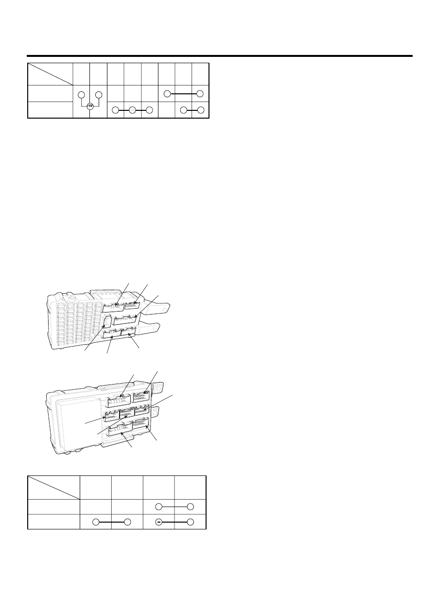
OFF
Illumination
ON
2
6
3
9
5
10
7
8
Terminal
Position
SCMBE6461L
HAZARD LAMP RELAY
1.
Disconnect the negative (-) battery terminal.
2.
Disconnect the passenger compartment.
3.
Check for continuity between terminals. There should
be continuity between the No.2 of I/P-C and No.3 or
No.4 of I/P-E terminals when power and ground are
connected to the No.2 of I/P-C and No.6 of I/P-G ter-
minals.
4.
There should be no continuity between the No.2 of
I/P-C and No.3 or No.4 of I/P-E terminals when power
is disconnected to the No.2 of I/P-C and No.6 of I/P-G
terminals.
A
G
H
B
D
L
J
K
F
N
M
E
C
SCMBE6462D
I/P-C
(2)
I/P-E
(3 or 4)
I/P-G
(6)
I/P-C
(2)
+
Power off
Power on
Terminal
Position
SCMBE6463L