Hyundai Santa Fe (2006 year). Manual - part 174


  Index      Hyundai     Hyundai Santa Fe - service repair manual 2006 year


Search            


Content   ..  172  173  174  175   ..


Hyundai Santa Fe (2006 year). Manual - part 174


WINDSHIELD DEICER

BE -157

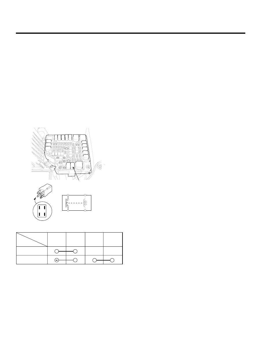
WINDSHIELD DEICER RELAY

INSPECTION

EF0EF7EE

1.

Disconnect the negative (-) battery terminal.

2.

Remove the windshield deicer relay from the engine
room relay box.

3.

There should be continuity between the No.30 and
No.87 terminal when power and ground are con-
nected to the No.85 terminal and No.86 terminal.

4.

There should be no continuity between the No.30
terminal and No.87 terminal when power is discon-
nected.

86

30

87

85

30

86

87

85

A

SCMBE6306D

85

86

30

+

87

Disconnected

Connected

Terminal

Power

SCMBE6307L

BE -158

BODY ELECTRICAL SYSTEM

REAR WINDOW DEFOGGER

COMPONENT LOCATION

EED7B9CA

1*

4*

2*

3

1.  Junction box (Rear window defogger)
2.  Rear window defogger switch

3.  Rear window defogger
4.  Body control module

The parts with asterisk(*) :
This illustration shows the LHD type.
RHD type is symmetrical.

SCMBE6310L

REAR WINDOW DEFOGGER

BE -159

REAR WINDOW DEFOGGER
PRINTED HEATER

INSPECTION

EF6BBBEE

CAUTION

Wrap tin foil around the end of the voltmeter test
lead to prevent damaging the heater line. Apply
finger pressure on the tin foil, moving the tin foil
along the grid line to check for open circuits.

Finger pressure

Tester probe

Tin foil

Printed
heater line

ETA9165A

1.

Turn on the defogger switch and use a voltmeter to
measure the voltage of each heater line at the glass
center point. If a voltage of approximately 6V is in-
dicated by the voltmeter, the heater line of the rear
window is considered satisfactory.

6 Volts (Normal)

+

-

ETA9165B

2.

If a heater line is burned out between the center point
and (+) terminal, the voltmeter will indicate 12V.

12 Volts

Burned out point

+

-

ETA9165C

3.

If a heater line is burned out between the center point
and (-) terminal, the voltmeter will indicate 0V.

0 Volts

+

-

Burned out point

ETA9165D

4.

To check for open circuits, slowly move the test lead
in the direction that the open circuit seems to ex-
ist. Try to find a point where a voltage is generated
or changes to 0V. The point where the voltage has
changed is the open-circuit point.

Voltage changes before and 
after open circuited point

Here is 0V voltage

Terminal
(-)

-

ETA9165E

BE -160

BODY ELECTRICAL SYSTEM

5.

Use an ohmmeter to measure the resistance of each
heater line between a terminal and the center of a grid
line, and between the same terminal and the center of
one adjacent heater line. The section with a broken
heater line will have a resistance twice as that in other
sections. In the affected section, move the test lead
to a position where the resistance sharply changes.

When measured from negative 
terminal side (Section 
with no broken grid line)

(Section with broken grid 
 line)   Center point

Positive 
teminal 
Tester B 
reads resistance 
twice as large as tester terminal

ETA9165F

REPAIR OF BROKEN HEATER LINE

Prepare the following items :

1.

Conductive paint.

2.

Paint thinner.

3.

Masking tape.

4.

Silicone remover.

5.

Using a thin brush :
Wipe the glass adjacent to the broken heater line,
clean with silicone remover and attach the masking
tape as shown. Shake the conductive paint container
well, and apply three coats with a brush at intervals of
about 15 minutes apart. Remove the tape and allow
sufficient time for drying before applying power. For a
better finish, scrape away excess deposits with a knife
after the paint has completely dried. (Allow 24 hours).

Masking tape

ETA9165G


Content   ..  172  173  174  175   ..