Hyundai Santa Fe (2006 year). Manual - part 173
WINDSHIELD DEICER
BE -153
WINDSHIELD DEICER
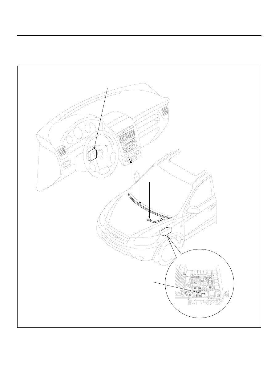
COMPONENT LOCATION
E58B0AF7
3
4*
2*
1*
1. Body control module
2. Windshield deicer switch
3. Windshield deicer
4. Deicer connector
5. Windshield deicer relay
5
The parts with asterisk(*) :
This illustration shows the LHD type.
RHD type is symmetrical.
SCMBE6300L