Hyundai Santa Fe (2006 year). Manual - part 14


  Index      Hyundai     Hyundai Santa Fe - service repair manual 2006 year


Search            


Content   ..  12  13  14  15   ..


Hyundai Santa Fe (2006 year). Manual - part 14


AT -8

AUTOMATIC TRANSAXLE (F4A51)

MECHANICAL SYSTEM

OPERATION COMPONENTS AND FUNCTION

Operating Element

Symbol

Function

Under drive clutch

UD

Connect input shaft and under drive sun gear

Reverse clutch

REV

Connect input shaft and reverse sun gear

Overdrive clutch

OD

Connect input shaft and over drive carrier

Low&Reverse brake

LR

Hold LR annulus gear and OD carrier

Second brake

2ND

Hold reverse sun gear

One way clutch

OWC

Restrict the rotating direction of low & reverse annulus gear
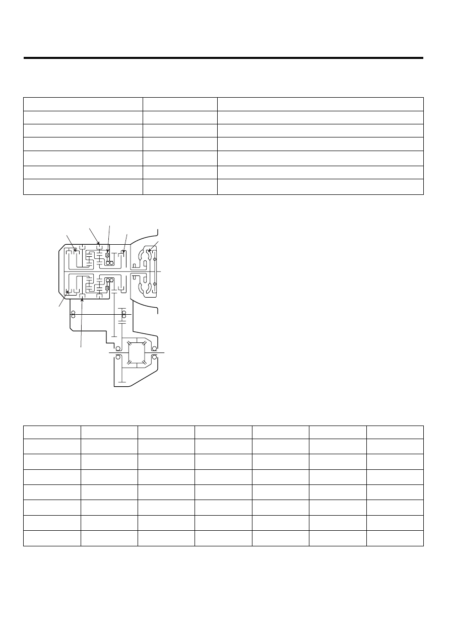
Reverse
clutch

Overdrive
clutch

Second
brake

Low&Reverse

brake

Underdrive
clutch

OWC

Torque
converter

EKRF002A

OPERATING ELEMENTS

UD/C

OD/C

REV/C

2ND/B

LR/B

OWC

P

R

N

D1

D2

D3

D4

1) ○ : OWC is operated when shifts from 1st gear to 2nd
gear.
2) L & R brake is released in 1st gear when the vehicle
speed is more than 5KPH approximately.

AUTOMATIC TRANSAXLE SYSTEM

AT -9

TORQUE CONVERTER AND SHAFT

The torque converter consists of an impeller(pump), tur-
bine and stator assembly in a single unit. The pump is
connected to the engine crankshaft and turns as the en-
gine turns. This drawing force is transmitted to the turbine
through the oil which is recycled by the stator.
The transmission has two parallel shafts ; the input shaft
and the output shaft. Both shafts are in line with the en-
gine crankshaft. The input shaft includes the overdrive
clutch, reverse clutch, underdrive clutch, one way clutch,
2ND brake, low&reverse brake, overdrive planetary car-
rier, output planetary carrier and transfer drive gear. The
output shaft includes the transfer driven gear.

CLUTCHES

The gear changing mechanism utilizes three multi-disc
clutches. The retainers of these clutches are fabricated
from high-precision sheet metal for lightness and ease
of production. Also, more responsive gearshifts at high
engine speeds are achieved by a pressure-balanced
piston mechanism that cancels out centrifugal hydraulic
pressure. This mechanism replaces the conventional ball
check valve.

UNDERDRIVE CLUTCH

The underdrive clutch operates in 1st, 2nd, and 3rd gears
and transmits driving force from the input shaft to the un-
derdrive sun gear(A).
The components comprising the under clutch are as illus-
trated below.
Hydraulic pressure acts in the piston pressure chamber(B)
(between the piston(c) and retainer) and thus pushes the
piston(C). In turn, the piston depresses the clutch discs
and thereby transmits driving force from the retainer(D) to
the hub(E) side.

E

D

C

B

A

EKRF002B

At high speed, fluid remaining in the piston pressure cham-
ber is subjected to centrifugal force and attempts to push
the piston.
However, fluid in the balance fluid chamber(A) (the space
between the piston and return spring retainer(B)) is also
subjected to centrifugal force.
Thus, the hydraulic pressure on one side of the piston can-
cels out the hydraulic pressure on the other side, and the
piston does not move.

B

A

EKRF002C

AT -10

AUTOMATIC TRANSAXLE (F4A51)

REVERSE CLUTCH AND OVERDRIVE CLUTCH

The reverse clutch(C) operates when the reverse gear is
selected and transmits driving force from the input shaft to
the reverse sun gear.
The overdrive clutch(D) operates in 3rd and 4th gears and
transmits driving force from the input shaft to the overdrive
planetary carrier and low-reverse annulus gear.

A

D

B

C

EKRF002D

BRAKES

The gear changing mechanism utilizes two multi-disc
brakes.

LOWREVERSE BRAKE AND SECOND BRAKE

The low & reverse brake(A) operates in 1st and reverse
gears, when the vehicle is parked, and during manual op-
eration. It locks the low&reverse annulus gear and over-
drive planetary carrier to the case.
The second(C) brake(B) operates in 2nd and 4th gears
and locks the reverse sun gear(D) to the case.
The components comprising the low&reverse brake and
second brake are as illustrated below.
As shown, the discs and plates of the two brakes are ar-
ranged on either side of the rear cushion plate(E), which
is itself secured to the case(F) by a snap ring.

EKRF002E

OWC

To improve the shift feeling from 1st to 2nd gear, OWC was
adopted on the low&reverse brake annulus gear. Instead
of hydraulic fixing by Low&reverse brake at the 1st gear,
this mechanical fixing device was used. This structure is
not a new concept, because this OWC already has been
installed on the previous models.

ACCUMULATORS

Number

Function Name

Color

1

Low&Reverse Brake

None

2

Underdrive Clutch

Yellow

3

Second Brake

Blue

4

Overdrive Clutch

None

1

2

3

4

EKRF002F

AUTOMATIC TRANSAXLE SYSTEM

AT -11

OBJECTIVE

* Energy (hydraulic pressure) storage
* Impact and pulsation damping when solenoid valves op-
erating
* Operation as spring element
* Smooth shifting by preventing sudden operation of
clutches and brakes

TRANSFER DRIVE GEAR

With the transfer drive gear, increased tooth height and a
higher contact ratio have reduced gear noise.
Also, the bearing that supports the drive gear is a pre-
loaded type that eliminates rattle, and the rigidity of the
gear mounting has been increased by bolting the bearing
directly onto the case.

Case

Case

Locking nut

EKRF002G

OUTPUT SHAFT/TRANSFER DRIVEN GEAR

As shown in the illustration below, the transfer driven gear
is press-fitted onto the output shaft, and the output shaft is
secured by a locking nut and supported by bearings.
The locking nut has a left-handed thread, and a hexagonal
hole in the other end of the shaft enables the shaft to be
held in position for locking nut removal.

Transfer
driven gear

Hexagonal hole
for locking of shaft

Locking nut

EKRF002H

MANUAL CONTROL SYSTEM

MANUAL CONTROL LEVER

The manual control lever is fitted to the top of the valve
body and is linked to the parking roller rod and manual
control valve pin.
A detent mechanism is provided to improve the gear shift
feeling during manual selection.

PARKING MECHANISM

When the manual control lever is moved to the parking
position, the parking roller rod moves along the parking
roller support and pushes up the parking sprag.
As a result, the parking sprag meshes with the transfer
driven gear (parking gear), thereby locking the output
shaft. To minimize the operating force required, a roller
is fitted to the end of the rod.

Inhibitor switch

Parking roller rod

Parking sprag

Parking gear

Parking roller
support

Detent spring

Manual control lever

Parking
roller rod

Parking roller 
support

Parking sprag

EKRF002I


Content   ..  12  13  14  15   ..