Hyundai Santa Fe (2006 year). Manual - part 11
MECHANICAL POWER STEERING SYSTEM
ST -41
EPNG006A
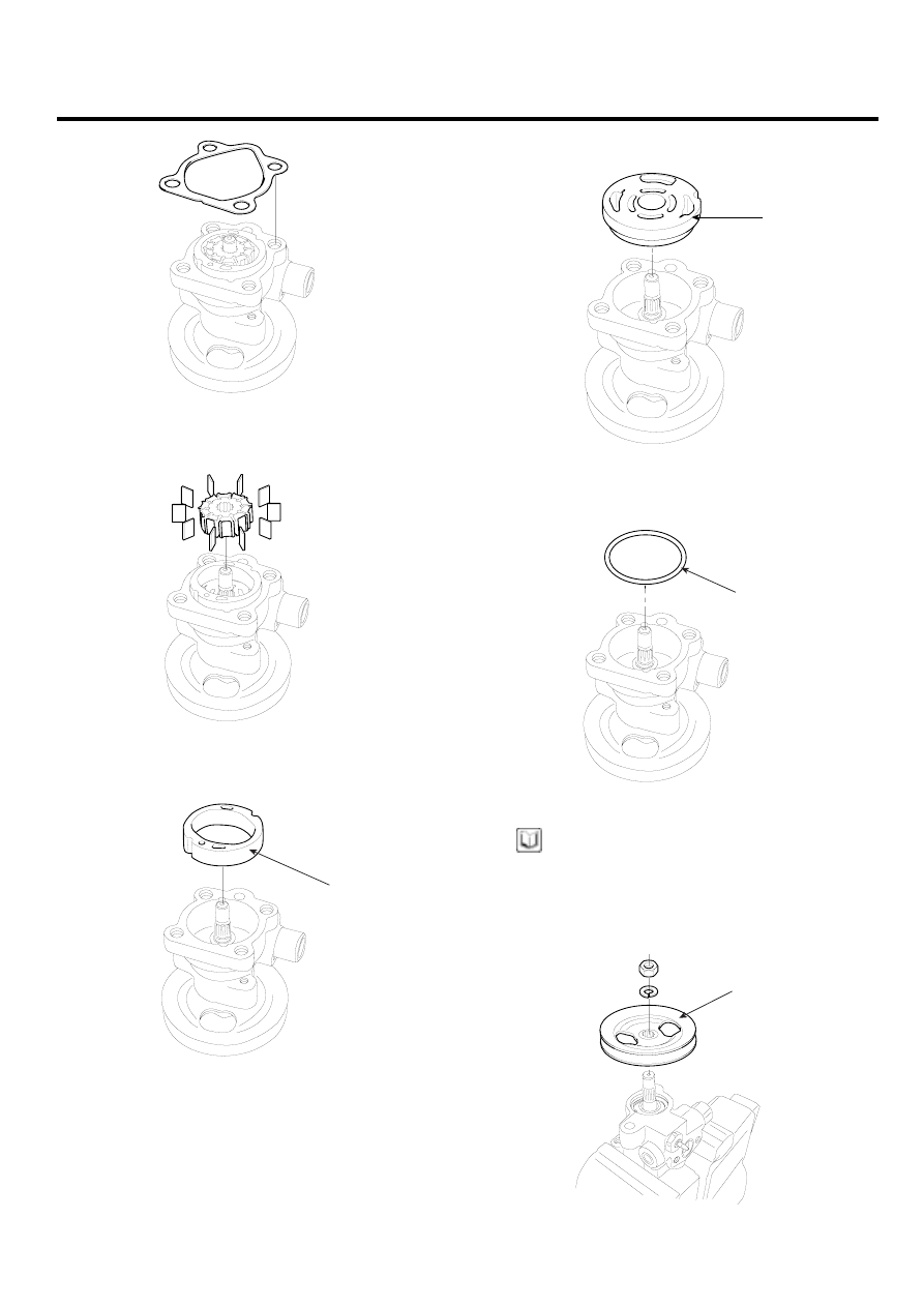
3.
Remove the rotor and vanes.
EPNG007A
4.
Remove the cam ring.
A
EPNG008A
5.
Remove the oil pump side plate (A).
A
BPKG501E
6.
Remove the inner and outer O-ring (A).
A
EPNG010A
NOTE
When assembling, use a new gasket and O-ring.
7.
Mount the pump in a vise and remove the pulley (A)
nut and the spring washer.
A
EPNG011A