Hyundai: Engine D4FA. Manual - part 4


  Index      Hyundai     Hyundai: Engine D4FA - service repair manual


Search            


Content   ..  1  2  3  4  5  ..


Hyundai: Engine D4FA. Manual - part 4


CHARGING SYSTEM

EEA -13

INSPECTION

EC7F1CDF

BATTERY DIAGNOSTIC TEST (1)
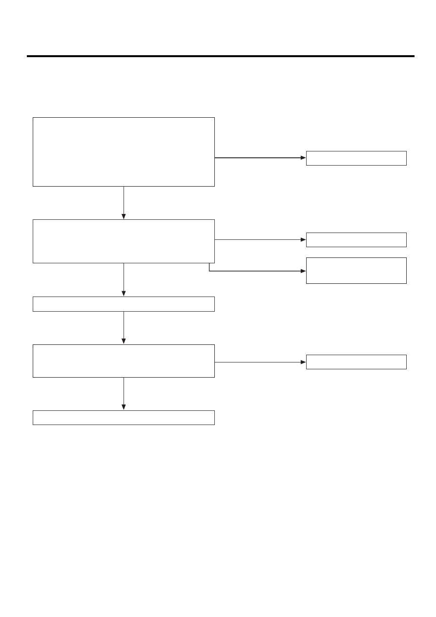
CHECKING FLOW

Step 1 : Visual inspection
Check for obvious damage such as a cracked or broken
terminal and case or cover that could permit leakage of
electrolyte.
Determine the cause of damage and correct as needed.
Clean any corrosion with as solution of baking soda and
water.

Replace battery

Replace battery

Replace battery

Step 2 : Measure battery voltage
Check the voltage after at least one day in case of
recharging the battery, and the recharging should be made
in accordance with the charging instructions.

Charge battery

Charging system inspection

Step 3 : Load test
Perform an eletrical load using the appropriate load test
amperage specifications for the battery.

Battery is good

Terminal & case of
cover damage,
electrolyte leakage

Below 11.0V

Above 12.5V

Refer to load test

OK

OK (11.0 ~ 12.4V)

OK

EEA -14

ENGINE ELECTRICAL SYSTEM(D4FA - DSL1.5)

LOAD TEST

1.

Perform the following steps to complete the load test
procedure for maintenance free batteries.

2.

Connect the load tester clamps to the terminals and
proceed with the test as follow:

1)

If the battery has been on charge, remove the
surface charge by connect a 300ampere load for
15 seconds.

2)

Connect the voltmeter and apply the specified
load.

3)

Read the voltage after the load has been applied
for 15 seconds.

4)

Disconnect the load.

5)

Compare the voltage reading with the minimum
and replace the battery if battery test voltage is
below that shown in the voltage table.

Voltage

Temperature

9.6V

20 C (68.0 F) and above

9.5V

16 C (60.8 F)

9.4V

10 C (50.0 F)

9.3V

4 C (39.2 F)

9.1V

-1 C (30.2 F)

8.9V

-7 C (19.4 F)

8.7V

-12 C (10.4 F)

8.5V

-18 C (-0.4 F)

NOTE

-

If the voltage is greater shown in the table, the
battery is good.

-

If the voltage is less than shown in the table, re-
place the battery.

BATTERY DIAGNOSTIC TEST (2)

1.

Make sure the ignition switch and all accessories are
in the OFF position.

2.

Disconnect the battery cables (negative first).

3.

Remove the battery from the vehicle.

CAUTION

Care should be taken in the event the battery case
is cracked or leaking, to protect your skin from the
electrolyte.
Heavy rubber gloves (not the household type)
should be wore when removing the battery.

EBJD008B

4.

Inspect the battery tray for damage caused by the loss
of electrolyte. If acid damage is present, it will be
necessary to clean the area with a solution of clean
warm water and baking soda. Scrub the area with a
stiff brush and wipe off with a cloth moistened with
baking soda and water.

5.

Clean the top of the battery with the same solution as
described above.

6.

Inspect the battery case and cover for cracks.

If

cracks are present, the battery must be replaced.

7.

Clean the battery posts with a suitable battery post
tool.

8.

Clean the inside surface of the terminal clamps with
a suitable battery cleaning tool. Replace damaged or
frayed cables and broken terminal clamps.

9.

Install the battery in the vehicle.

10. Connect the cable terminals to the battery post, mak-

ing sure tops of the terminals are flush with the tops
of the posts.

CHARGING SYSTEM

EEA -15

11. Tighten the terminal nuts securely.

12. Coat all connections with light mineral grease after

tightening.

CAUTION

When batteries are being charged, an explosive
gas forms beneath the cover of each cell.

Do

not smoke near batteries being charged or which
have recently been charged. Do not break live cir-
cuit at the terminals of batteries being charged.
A spark will occur when the circuit is broken.
Keep open flames away from battery.

EBJD008A

EEA -16

ENGINE ELECTRICAL SYSTEM(D4FA - DSL1.5)

STARTING SYSTEM

DESCRIPTION

E6CD00C1

The starting system includes the battery, starter, solenoid
switch, ignition switch, inhibitor switch (A/T), ignition lock
switch, connection wires and the battery cable.
When the ignition key is turned to the start position, current
flows and energizes the starter motor’s solenoid coil.
The solenoid plunger and clutch shift lever are activated,
and the clutch pinion engages the ring gear.
The contacts close and the starter motor cranks. In order
to prevent damage caused by excessive rotation of the
starter armature when the engine starts, the clutch pinion
gear overruns.

Solenoid

Brush assembly

Armature

Overrun clutch

STARTER CIRCUIT

TROUBLESHOOTING

E9CCB56A

NOTE

The battery must be in good condition and fully
charged.

1.

Remove the fuel pump relay from the fuse box.

A

ABGE002A

2.

With the shift lever in N or P (A/T) or clutch pedal
pressed (M/T), turn the ignition switch to "START"

If the starter normally cranks the engine, starting sys-
tem is OK. If the starter will not crank the engine at
all, go to next step.

If it won’t disengage from the ring gear when you re-
lease key, check for the following until you find the
cause.

• Solenoid plunger and switch malfunction.
• Dirty pinion gear or damaged overrunning clutch.

3.

Check the battery condition. Check electrical connec-
tions at the battery, battery negative cable connected
to the body, engine ground cables, and the starter for
looseness and corrosion. Then try starting the engine
again.

If the starter cranks normally the engine, repairing the
loose connection repaired the problem. The starting
system is now OK.
If the starter still does not crank the engine, go to next
step.

4.

Disconnect the connector from the S-terminal of so-
lenoid. Connect a jumper wire from the B-terminal of
solenoid to the S-terminal of solenoid.

If the starter cranks the engine, go to next step.
If the starter still does not crank the engine, remove
the starter, and repair or replace as necessary.


Content   ..  1  2  3  4  5  ..