Geely EC718, EC718RV, EC715, EC715RV. Manual part - 168


  Главная      Geely     Geely Emgrand EC718, EC718RV, EC715, EC715RV. Workshop Manual year 2009


поиск по сайту            


содержание   ..   164  165  166  167  168  169 ..


Geely EC718, EC718RV, EC715, EC715RV. Manual part - 168


2.12.2 Description and Operation
2.12.2.1 Overview

4G15D  uses  Delphi  MT80  Engine  Control  System.  Its  main
characteristic is that the engine control module (ECM) is the
core  system.  The  traditional  mechanical  throttle  pedal  and
mechanical  throttle  body  are  replaced  by  more  advanced
electronic throttle acceleration pedal sensor assembly and the
electronic throttle body assembly. Due to adopt this system,
ECM  control  over  the  engine  torque  is  more  convenient.  In
addition,  MT80  control  system  also  incorporates  multi-point
sequential fuel injection, group direct ignition without electricity
distributions,  variable  valve  timing  control  and  three-way
catalytic  converter  processing,  to  meet  the  increasingly
stringent emission regulations.

System main functions includes:

1. Engine torque output control mode: ECM calculated the gas

flow through the intake air temperature sensor and intake
manifold pressure sensor signals, so that the Air-Fuel ratio
is  closer  to  the  current  engine  operating  conditions
demand.

2. Torque  control  mode:  ECM  calculates  the  output  torque

required and controls the engine output power, according
to the acceleration pedal position sensor signal.

3. Main relay control.

4. Close-loop  control  multi-point  sequential  fuel  injection:  A

close-loop fuel control can precisely control the engine Air-
Fuel ratio, therefore efficiently controls emissions. Close-
loop control can effectively eliminate the system and related
mechanical  components  wear  and  tear  due  to
manufacturing error and improves vehicle consistency.

5. Variable Valve Timing (VVT) control: Variable valve timing

control  system  uses  VVT  actuator  to  change  the  intake
camshaft  and  the  crankshaft  relative  positions.  Engine
power  management  system  calculates  the  best  valve
timing based on engine operating conditions, and controls
VVT solenoid valve movement, allowing oil pressure, flow
and  direction  to  change,  and  ultimately  promoting  the
camshaft movement to the desired position.

6. Fuel control without fuel return.

7. Fuel pump control.

8. ECM has built-in ignition drive module, without electricity

distinction group direct ignition.

9. Knock  Control:  When  the  knock  sensor  detects  a  knock

occurring,  the  system  will  calculate  the  ignition  advance
angle delay based on the current conditions, knock intensity
and  other  necessary  information,  and  defers  the  ignition
advance angle, so as to avoid or reduce knock. Electronic
Throttle  Control:  Since  the  system  uses  an  electronic
throttle idle speed control, highly precise idle control can be
achieved. Such as the electrical load compensation, when
there  are  electrical  loads  or  the  load  is  cut  off,  due  to  a
sudden increase or decrease in engine load, resulting in
engine speed fluctuation in a certain range, this increases
the  electrical  load  control  adjustments.  When  the  load
increases or decreases, the air flow rate and (or) the ignition
advance angle will be adjusted accordingly, so that the idle
speed remains steady.

10. Canister solenoid valve control

11. Cooling fan relay control

12. System  self-diagnostic  function:  After  the  system  enters

into  working  condition,  ECM  controls  all  system
components working, and tests them in real time. Once the
system or component malfunction occurs, the system will
light up the engine malfunction lamp to remind the driver to
repair or service the vehicle on time. In the mean time ECM
will start fault protection mode.

13. System  voltage  over  load  protection:  When  the  charging

system malfunction causes the voltage too high, the system
will enter protection mode to restrict the engine speed to
prevent ECM damage.

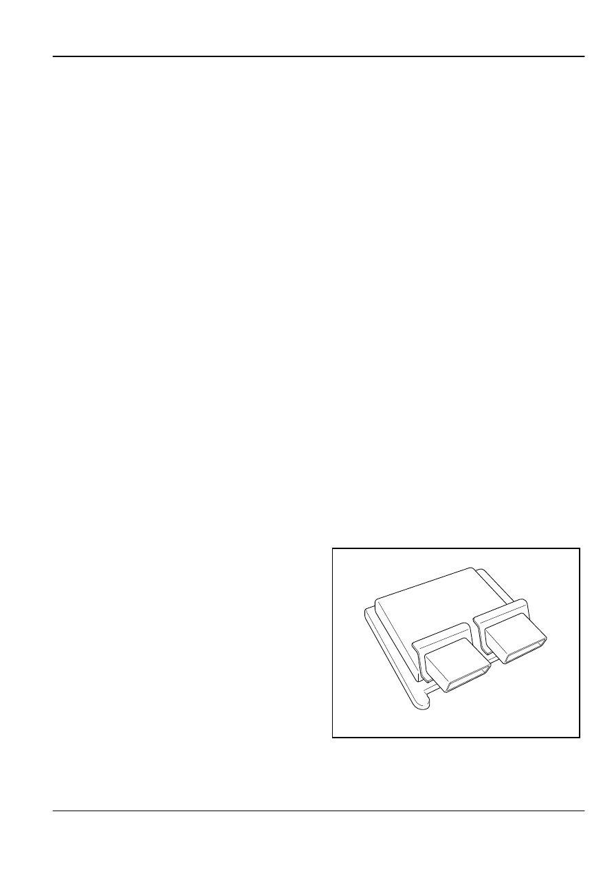
2.12.2.2 Components Descriptions

1. Engine Control Module (ECM)

FE02-8031b

Engine

Control System JL4G15-D

2-587

Engine control module is a core microprocessor with a a micro
chip  controller.  Its  function  is  to  process  data  from  various
vehicle sensors to determine the engine's working condition,
and through the various actuators controls engine actuators.
ECM normal working voltage is 9.0 V-16 V

Note

Although  ECM  has  the  voltage  over  load  and  reverse
polarity  voltage  protection  function,  during  the  repair
process  it  is  prohibited  to  connect  the  battery  positive
and negative wrong or apply voltage higher than 15V.
Otherwise,  it  will  cause  damage  to  ECM  and  other
electrical equipments.

2. Crankshaft Position Sensor (CKP)

FE02-5121b

The  crankshaft  position  sensor  output  can  be  used  to
determine crankshaft position and rotation speed. Crankshaft
position sensor is a magnetic-electric sensor, which is installed
in the front end of the transmission housing, and tightened with
bolts, below the coolant temperature sensor. Flywheel signal
plate  and  the  crankshaft  sensor  is  an  integrated  part.  The
sensor and the signal plate tooth gap in between 0.3 and 1.5
mm  (0.01-0.06  in).  The  signal  plate  has  58  machined  slots.
When  the  crankshaft  rotates,  58X  tooth  tip  and  the  alveolar
passes through the sensor from different distances. The sensor
senses  the  reluctance  change,  the  alternating  reluctance
generates an alternating output signal. The 58X gear plate gap
position aligns with engine top dead center. When the cylinder
No.1 reaches top dead center, The sensor aligns with the 20th
tooth lower edge. ECM uses this signal to determine crankshaft
position and rotation speed.
Sensor Resistance: 500 Ω-610 Ω
Output Voltage: 400 mV when 60 rpm. The voltage increases
as the speed increases.

3.  Intake  Manifold  Pressure  /  Temperature  Sensor
(MAP / IAT)

FE02-8032b

This sensor detects intake manifold pressure change caused
by  engine  load  and  speed  changes.  These  changes  will  be
converted to the voltage output. When the engine decelerates,
the  throttle  body  closes  resulting  in  a  relatively  low  intake
manifold  absolute  pressure  output.  Intake  manifold  absolute
pressure and vacuum degree is opposite. When the manifold
pressure is high, the vacuum is low. MAP sensor is also used
to  measure  atmospheric  pressure.  This  measurement  is
calculated as part of the MAP calculation. When the ignition
switch is turned on and the engine is not running, the engine
control  module  reads  atmospheric  pressure  as  the  intake
manifold pressure, and adjusts the Air-Fuel ratio accordingly.
With  this  kind  of  altitude  compensation,  the  system  can
maintain a low emissions while maintaining maneuverability.
Sensor signal passes through ECM harness connector EN01
terminal  No.19  to  ECM.  When  MAP  sensor  and  its  circuit
malfunction occurs, DTC P0105, P0106, P0107, P0108 will be
recorded.

2-588

Control System JL4G15-D

Engine

4. Camshaft Position Sensor (CMP)

FE02-5362b

Camshaft  position  sensor  is  a  Hall-effect  sensor,  which  is
installed  in  the  vicinity  of  the  intake  camshaft,  and  works
together  with  camshaft  signal  wheel.  The  signal  wheel  is
corresponding to the specific engine location. ECM measures
digital voltage signal through the sensor, therefore determining
the  working  cylinder  and  to  implement  one  to  one  control.
Engine control module then calculates the actual sequence of
fuel  injection.  If  the  engine  is  running  when  the  camshaft
position sensor signal is lost, the fuel injection system will be
converted to fuel injection order based on the final fuel injection
pulse, while the engine continues to run. If the engine starts
after being shut down, the fuel injection will be converted from
sequential injection to group injection. Even if the fault exists,
the engine can be restarted.

5. Engine Coolant Temperature Sensor (ECT)

FE02-5127b

Engine coolant temperature (ECT) sensor is used to detect the
engine operating temperature. ECM provides the best control
scheme  depending  on  the  temperature.  The  sensor  uses  a

negative  temperature  coefficient  thermistor  as  the  sensing
element, when the coolant temperature rises, the resistance
decreases. At -30 ° C (-22 ° F) the resistance is 26000 Ω; at
130  °  C  (266  °  F),  the  resistance  is  90  Ω.  The  sensors  is
installed  in  the  main  coolant  path.  The  coolant  temperature
signal  is  important  to  the  ignition  timing  and  fuel  injection
adjustment,  while  the  signal  is  also  transmitted  to  the
instrument panel (IP) through the CAN network, used to display
the current engine working temperature.

6. Knock Sensor (KS)

FE02-5125b

Knock sensor is a frequency response sensor, installed in the
engine  block  the  most  sensitive  to  knocking  part,  the  lower
intake  manifold.  ECM  uses  knock  sensor  to  detect  knock
intensity,  and  then  to  adjust  the  ignition  advance  angle,  to
effectively control knocking and optimize the engine power, fuel
economy and emission levels. If the engine knocking occurs,
ECM will receive the signal, filter out the non-knock signals and
determine engine cycle calculated by camshaft and crankshaft
position sensor signals. ECM determines the cylinder in which
the knock occurs and will delay the ignition advance angle for
this cylinder until the knock disappears. Then ECM advances
the ignition advance angle until the ignition angle is best suited
for the operating conditions at that time.
Due to weak sensor signals, the sensor wire has a shielded
cable. Its resistance is 1M Ω, in any case the output signal is
greater than 17mV / g

Engine

Control System JL4G15-D

2-589

7. Oxygen Sensor (HO2S)

FE02-5129b

Oxygen  sensor  is  an  important  sensor  in  a  close-loop  fuel
control system, which adjusts and maintains the ideal Air-Fuel
ratio, so that three-way catalytic converter achieves the best
conversion  efficiency.  When  the  mixture  Air-Fuel  ratio
becomes lean, the oxygen content in the exhaust increases,
and oxygen sensor output voltage is reduced. On the contrary,
the output voltage increase feedback to ECM indicates the air-
fuel ratio.
Oxygen  sensor  sensing  material  is  zirconia,  hollow  with  an
external sensing part. When Zirconia components are heated,
they  are  activated,  reference  air  enters  the  hollow  parts  of
zirconium  oxide  from  the  wire.  Exhaust  passes  through  the
outer electrode, oxygen ions move from the center of zirconia
to the outer electrode, thus consisting a simple atomic battery
with  a  voltage  between  two  electrodes.  According  to  the
oxygen concentration in the exhaust, Zirconium oxide changes
the output voltage, and thus determining the oxygen content in
the  exhaust.  Usually  the  exhaust  oxygen  sensor  design
generates a voltage amplitude jump in the vicinity of the Air-
Fuel ratio (14.6:1) to help ECM to determine the exact Air-Fuel
ratio. Pre-Catalytic oxygen sensor is installed in the exhaust
manifold,  the  three-way  catalytic  converter  front  end.  Post-
Catalytic oxygen sensor is installed in the three-way catalytic
converter rear end. When the mixture is rich, the output voltage
is 750 mV. When the mixture is lean, the output voltage is less
than 200 mV. When the mixture becomes rich from lean, the
responding time is less than 75 ms. When the mixture becomes
lean from rich, the responding time is less than 150 ms.

8. Fuel Injectors

FE02-5131b

The  injector  structure  is  an  electromagnetic  switch  valve
device. The coil form poles leads to the engine wiring harness
and ECM and is connected to power supply. When the coil is
controlled  by  ECM  to  connect  to  the  system  ground,  the
resulting  magnetic  force  overcomes  the  spring  force,  fuel
pressure and manifold vacuum suction, and draws the valve
core. The fuel sprays through the valve seat hole to the guide
hole as a mist type spraying into the intake valve. When the
power supply is cut off, the magnetic force disappears, with the
spring force and fuel pressure, the injector closes.
The top of the fuel injector rubber seal and the fuel rail form a
reliable fuel pressure seal; the lower part of the same rubber
seal and the engine air intake manifold form an air seal. Fuel
injector resistance is 11.6-12.4 Ω.

Note

When the fuel injector is blocked or not closed tight, the
engine malfunction lamp may be lit, but the detection of
DTC  code  is:  oxygen  sensor  distortion,  erratic  signal,
such  as  Air-Fuel  ratio  is  not  normal  fault.  At  this  time
component  malfunction  should  be  carefully  judged.
Because when the fuel injector is blocked or leaking, the
amount of fuel injected is not controlled by the ECM pulse
width control. The oxygen sensor feedback to ECM will
be very different from the ECM control target. When ECM
detects this signal, it will determine the oxygen sensor is
not working properly. But the system can not determine
whether  the  fault  is  the  oxygen  sensor  itself  or  other
associated  parts.  Therefore  when  diagnose  such  a
malfunction,  the  malfunction  component  must  be
carefully identified.

2-590

Control System JL4G15-D

Engine


содержание   ..   164  165  166  167  168  169 ..