Geely FC. Manual part - 25


  Главная      Geely     Geely FC. Workshop Manual year 2008


поиск по сайту          


содержание   ..  20  21  22  23  24  25  26  ..


Geely FC. Manual part - 25


16.

Remove front stabilizer bar.

(a) Remove 4 bolts, bracket and bush.

(b) Remove stabilizer bar.

17.

Install front stabilizer bar.

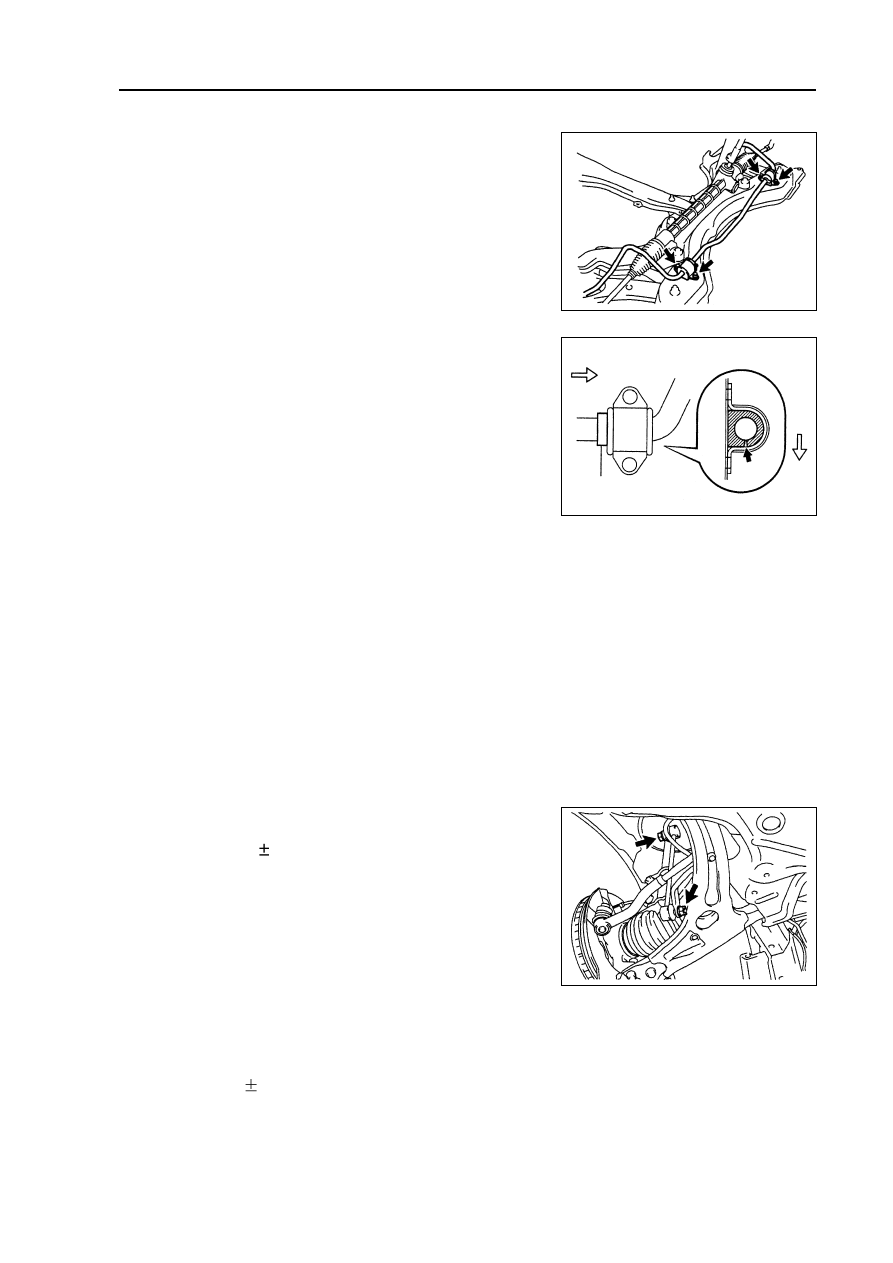
(a) Install bracket and bush with 4 bolts.

Hint: install bush to bush stop ring outside of

stabilizer bar.

18.

Install sub frame assembly [64000087]

(see Page 205).

Front suspension - Front stabilizer bar

19.

Connect lower left control arm assembly [64000091] (see Page 94).

20.

Connect lower right control arm assembly [64000092] (see Page 94).

21.

Connect power steering oil pipe assembly (see Page 205).

22.

Connect steering oil return pipe (see Page 205).

23.

Connect left side transversal lever  assembly (see Page 113).

24.

Connect right side transversal lever assembly (see Page 113).

25.

Install front left stabilizer link assembly

[64000097].

(a) Install front stabilizer link with 2 nuts.

Torque: 74

5 N.m

Hint: if ball joint rotates with nuts, please fix bolts with

hexagonal wrench (6mm).

26.

Install front right stabilizer link assembly

[64000097].

Hint: the installation procedures of right side are the

same as that of left side.

27.

Install right engine bottom shield.

28.

Install left engine bottom shield.

29.

Install front wheels.

Torque: 103

10 N.m

97

Rear

side

Bush stop ring

Outside

30.

Connect steering sliding shaft (see Page 205).

31.

Check front wheel center line.

32.

Install dust cover inside steering column.

33.

Refill power steering oil (see Page 200).

34.

Discharge air of power steering oil (see Page 200).

35.

Check there is oil leakage.

36.

Check and adjust front wheel alignment (see Page 87).

Front suspension - Front stabilizer bar

98

Front suspension - Front left lower control  arm ball joint assembly

Front left lower control arm ball joint assembly

Replacement

Hint: the replacement procedures of right side are the same as that of left side.

1. Remove front wheels.

2. Remove front left shaft hub nuts (see Page 123).

3. Disassemble front left speed sensor assembly [67000020] (see Page 123).

4. Disassemble front left brake wheel pump assembly and brake block (see Page 141).

5. Remove front left brake assembly [64000134] (see Page 141).

6. Disassemble left side transversal lever assembly (see Page 123).

7. Disassemble lower left control arm assembly [64000091] (see Page 94).

8. Remove front left shaft hub assembly (see Page 123).

9. Remove lower left control arm ball joint assembly [64000093] (see Page 123).

10.

Check lower left control arm ball joint assembly [64000093].

(a) As shown in the diagram, before installing nuts, shake

joint bolts forward and backward 5 times.

(b) Shake nuts continuously with torque wrench at the

speed of one circle per 2~4 s, and then read out torque

value at the 5

th

 circle.

Rotating torque: 1.0~4.9 N.m

11.

Install lower left control arm ball joint assembly

[64000093] (see Page 123).

12.

Install front left shaft hub assembly

(see Page 123).

13.

Install lower left control arm assembly [64000091] (see Page 123).

14.

Install left side transversal lever assembly (see Page 123).

15.

Install front left brake assembly [64000134] (see Page 141).

16.

Install front left brake wheel pump assembly and brake block (see Page 141).

17.

Install front shaft hub nuts (see Page 123).

18.

Install front wheels.

Torque: 103

10 N.m

19.

Check and adjust front wheel alignment (see Page 87).

20.

Check ABS sensor signal.

99

Rear suspension - rear suspension system

Rear suspension

Rear suspension system

Table on trouble occurrence

This table could help you find out failure causes, and each figure in the table indicates the possible

sequence of failure causes, please check every part as the sequence, and replace if necessary.

     Trouble occurrence

                            Possible trouble part

       Pages to refer to

1. Tire (abrasion or improper tire pressure)

109

  Wandering

2. Wheel alignment (incorrect)

101

3. Shaft hub bearing (abrasion)

129

4. Suspension parts (abrasion)

  -

1. Vehicle (overload)

  -

  Bottoming

2. Spring (elastic fatigue)

102

3. Absorber (abrasion)

102

  Swaying left and right/

1. Tire (abrasion or improper tire pressure)

109

  shaking forward and

2. Rear stabilizer bar (bending or breakage)

105

  backward

3. Absorber (abrasion)

102

1. Tire (abrasion or improper tire pressure)

109

  Rear wheel shimmy

2. Wheel (poor balance)

109

3. Absorber (abrasion)

102

4. Wheel alignment (incorrect)

101

1. Tire (abrasion or improper tire pressure)

109

  Abnormal tire abrasion

2. Wheel alignment (incorrect)

101

3. Absorber (abrasion)

102

4. Suspension parts (abrasion)

  -

100


содержание   ..  20  21  22  23  24  25  26  ..