Geely FC. Manual part - 22


  Главная      Geely     Geely FC. Workshop Manual year 2008


поиск по сайту            


содержание   ..  16  17  18  19  20  21  22  23  ..


Geely FC. Manual part - 22


Starting and charging - Starter components

Starter components

Replacement

1. Remove engine lower left shield.

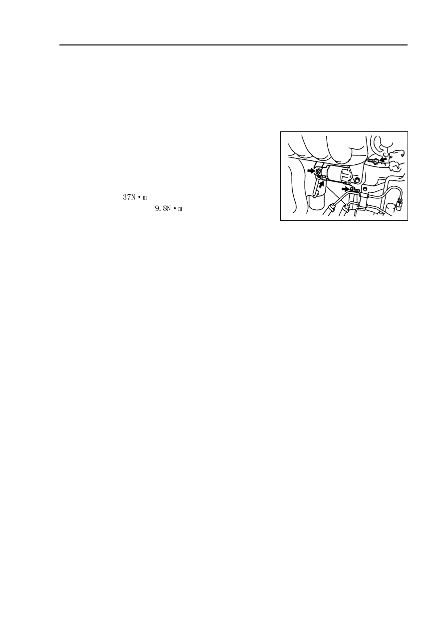
2. Remove starter components.

(b) Uncouple starter joint.

(b) Remove nuts, and uncouple starter wire.

(c) Remove 2 bolts and starter.

3. Install Starter components.

Torque:

bolt:  

Wire harness:  

85

Front suspension - front suspension system

Front suspension

Front suspension system

Table on trouble occurrence

This table could help you find out failure causes, and each figure in the table indicates the possible

sequence of failure causes, please check every part as the sequence, and replace if necessary.

Trouble occurrence

Possible trouble part

Pages to refer to

1. Tire (abrasion or improper tire pressure)

109

2. Wheel alignment (incorrect)

87

Deflection/single side

3. Steering linkage (looseness or abrasion)

-

4. Shaft hub bearing (abrasion)

123

5. Suspension parts (abrasion)

-

6. Steering gear (poor adjustment or breakage)

-

1. Vehicle (overload)

-

Bottoming

2. Spring (elastic fatigue)

90

3. Absorber (abrasion)

90

1. Tire (abrasion or improper tire pressure)

109

Swaying left and right/

2. Stabilizer bar (bending or breakage)

96

shaking forward and backward 3. Absorber (abrasion)

90

1. Tire (abrasion or improper tire pressure)

109

2. Wheel (poor balance)

109

3. Absorber (abrasion)

90

Front wheel shimmy

4. Wheel alignment (incorrect)

87

5. Ball joint (abrasion)

99

6. Shaft hub bearing (looseness or abrasion)

123

7. Steering linkage (looseness or abrasion)

-

8. Steering gear (poor adjustment or breakage)

-

1. Tire (abrasion or improper tire pressure)

109

Abnormal tire abrasion

2. Wheel alignment (incorrect)

87

3. Absorber(abrasion)

90

4. Suspension parts (abrasion)

-

86

Front suspension - Front wheel alignment

Front

Rear

If toe-in is not within specification, please adjust left and

right levers of steering gear.

4. Adjustment of toe-in

(a) Remove dust cover fixing clip.

Front

Rear

Toe-in

(Total)

Front wheel alignment

Adjustment

1. Inspection

(a) Check tire is worn and inflation pressure is proper.

Tire inflation pressure under normal temperature:

Tire size

Front and rear kPa

*1 It is used under the condition of speed below 160 km/h.

*2 It is used under the condition of speed above 160 km/h.

(b) Check tire run-out with dial indicator.

Tire run-out: 

3.0mm.

2. Measurement of vehicle height

Vehicle height:

(General road)

(Coarse road)

Measuring point:

A. Height for ground and front wheel center

B. Height for ground and bolt center in front of lower

control arm

C. Height for ground and fixed bolt center of rear axle beam

D. Height for ground and rear wheel center

Note: adjust vehicle height to standard value before checking front wheel alignment.

If vehicle height does not conform to regulations, please shake upward and downward or lift vehicle

body to adjust vehicle height.

3. Inspection of toe-in

Toe-in:

Front

87

          Inside wheel

38

o

45

2

o

Outside wheel: reference

32

o

50

Front suspension - Front wheel alignment

(Coarse road)

          Inside wheel

39

o

05

2

o

Outside wheel: reference

33

o

10

Camber

-0 31’

45’

Left-right error

45’

Caster

2 42’

45’

Left-right error

45’

Steering shaft inclination

18’

45’

Left-right error

45’

Camber

-0 18’

45’

Left-right error

45’

Caster

2 30’

45’

Left-right error

45’

Steering shaft inclination

10 52’

45’

Left-right error

45’

A: inside
B: outside

Front

Gauge

    If caster and steering axis inclination are not within specification, please adjust the caster and

then check parts of lower control arm is damaged or worn.

(b) Loosen lock nuts at the end of transversal lever  .

(c) Evenly rotate end levers of left and right rack to

adjust toe-in.

Hint: try adjusting toe-in to medium value.

(d) Ensure that the end lever length of left rack equals that

of right rack.

(e) Tighten lock nuts at the end of transversal lever.

Torque: 74

5 N.m

(f) Install dust cover fixing clip.

Hint: ensure that the dust cover does not distort.

5. Inspection of turning angle

(a) Completely rotate steering wheel to the bottom and then

measure turning angle.

Turning angle:

(General road)

(Coarse road)

Wheel

alignment

tester

88

If left and right inside wheels are not within specification, please check the end lever length of left rack

and right rack.

6. Inspection of camber, caster and steering shaft inclination

(a) Install camber-caster-kingpin gauge or erect wheel alignment tester.

(b) Check camber, caster and steering-axis inclination.

Camber, caster and steering shaft inclination:

(General road)


содержание   ..  16  17  18  19  20  21  22  23  ..