Geely FC. Manual part - 17


  Главная      Geely     Geely FC. Workshop Manual year 2008


поиск по сайту            


содержание   ..  10  11  12  13  14  15  16  17  18  ..


Geely FC. Manual part - 17


Exhaust - Exhaust pipe assembly

Exhaust

Exhaust pipe assembly

Removing, installing and disassembling, assembling

1. Remove oxygen sensor.

(a) Uncouple oxygen sensor joint.

(b) Remove oxygen sensor.

2. Remove exhaust pipe guard [64000051].
3. Remove front exhaust pipe together with three-way catalytic converter assembly

[64000042].

4. Remove middle exhaust pipe together with middle silencing device assembly [64000043].
5. Remove rear exhaust pipe together with rear silencing device assembly [64000044].
6. Install front exhaust pipe together with three-way catalytic converter assembly [64000042].

(a) Measure free length of compression spring with vernier caliper.

Free length:  43mm

Hint:  if the free length does dot reach the standard value, it is necessary to replace compres-

sion spring.

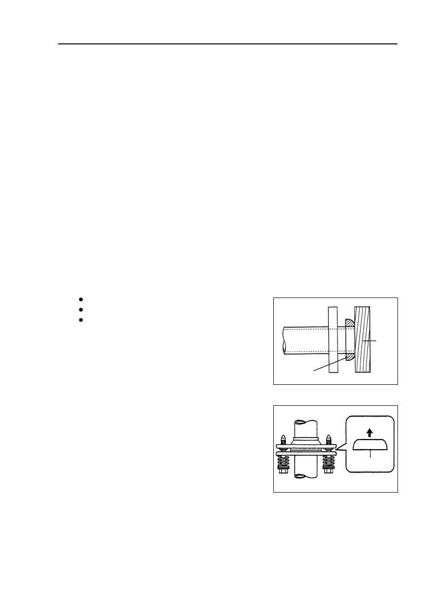
(b) Gently knock silencing device inlet seal ring to exhaust manifold with hammer and wooden block until

the surfaces are parallel and level with each other.

Notes:

Gently knock gasket toward positive direction.

Do not repeat using the gasket that has been removed.

Do not push the gasket in by means of tightening

bolt connection.

(c) Install exhaust pipe.

Torque:  43 N.m

7. Install oxygen sensor.

Torque:  44 N.m

9. Install rear exhaust pipe together with rear guard

assembly [64000044].

(a) Measure free length of compression spring with vernier

caliper.

Free length:  40mm

Hint: if the free length does dot reach the standard value, it is necessary to replace com-

pression spring.

(b) Install tail pipe to front pipe using a new gasket.

Torque:  43 N.m

10.

Install front exhaust pipe guard [64000051].

11.

Check there is gas leakage with exhaust system.

wooden

block

Gaskett

8. Install middle exhaust pipe together with middle si-

lencing device  assembly [64000043].

Couple front intake pipe of middle exhaust pipe together with

middle silencing device  assembly with outlet pipe of front ex-

haust pipe together with three-way catalytic converter using a

new gasket.Torque:  43 N.m

Tail pipe side

Gasket

65

Cooling  - Cooling syste

2. Check engine coolant level in reservoir.

Engine coolant level should be between “Low” and “Full” mark line.

Hint:  if the level is too low, check there is leakage and refill coolant to “Full” mark line.

3. Check engine coolant quality.

(a) Remove radiator cap.

Warning: when the temperature of engine and radiator is high, do not remove radiator cap to

avoid being scalded, because coolant and steam will spurt under high pressure.

(b) Check there is too much rust deposit around radiator cap or at outlet and check there is flake; there

should not be oil in the coolant.

Hint:  if coolant is too dirty, it is required to replace coolant.

(c) Install back radiator cap.

Inspection

1. Temperature regulator

Hint: the figure on temperature regulator is the

opening temperature of valve.

Cooling

Cooling system

On-vehicle inspection

1. Check there is leakage with cooling system.

Warning: when the temperature of engine and radiator is

high, do not remove radiator cap to avoid be-

ing scalded, because coolant and steam will

spurt under high pressure.

(a) Refill coolant to radiator, and install radiator cap tester.

(b) Preheat engine.

(c) Pump tester to make pressure go up to 118KPa, and check

the pressure falls.

Hint: if the pressure falls, check there is leakage with

hose, radiator or water pump, and check heater,

cylinder body and cylinder head if no external leak-

age is found.

66

Cooling  - Cooling syste

Temperature

Degree of valve opening

(a) Immerse temperature regulator into water and heat

gradually.

(b) Check opening temperature of valve.

Opening temperature of valve:  80

84

Hint: if opening temperature of valve is not within

specified range, it is required to replace tempera-

ture regulator.

(c) Check opening of valve.

Opening of valve:

2. Radiator cap assembly

Notes:

If radiator is dirty, wash it with clean water.

Before using radiator cap tester, dampen relief valve

and pressure valve with coolant or water.

(a) Use radiator cap tester to slowly pump radiator cap

tester, and check the air is released by vacuum valve.

Pumping speed:  1 time /(3 seconds or more)

Note:  pump radiator tester with constant speed.

Hints:

Pumping speed:  1 time /(3 seconds or more)

If air could not be released by vacuum valve,

please replace radiator cap.

(b) Pump tester and check opening pressure of relief valve.

Standard opening pressure:  74-108KPa

Min. opening pressure:  59KPa

Note: pumping speed means that the speed could be increased after the first time pumping

speed (to close vacuum valve).

Hints:

Pumping speed:  1 time within 1 second

Max. reading of tester is opening pressure.

If opening pressure is less than min. value, please replace radiator cap.

Hint: if degree of valve opening is not within speci-

fied range, it is required to replace tempera-

ture regulator.

(a) When temperature regulator is at low temperature (below

), check valve is tightly closed.

Hint: if the valve could not be closed, it is required to

replace temperature regulator.

67

Cooling  - Cooling fan system

Cooling fan system

On-vehicle inspection

1. Check cooling fan function at low temperature (below 95

).

(a) Turn ignition switch to ON.

(b) Check cooling fan is stopped.

Hint: if it is not stopped, check cooling fan relay and water temperature sensor, or check the

joint or wire harness between them.

(c) Uncouple water temperature sensor joint.

(d) Check cooling fan runs.

If it does not run, check fuse, cooling fan relay, engine ECU and cooling fan, or check there is short

circuit between them.

(e) Connect back water temperature sensor joint.

2. Check cooling fan function at high temperature (above 95

).

(a) Start engine and increase coolant temperature up to above 

Hint:  water temperature is the value measured by water temperature sensor on water outlet.

(d) Check cooling fan runs.

Hint:  if it does not run, please replace water temperature sensor.

3. Check cooling fan.

(a) Uncouple cooling fan joint.

(b) Connect battery and ampere meter to cooling fan joint.

(c) Check cooling fan runs normally and check ampere meter reading.Standard current:  7 12A

(d) Connect back cooling fan joint.

Inspection

1. Electronic fan relay  [67000064]

2. Electronic fan relay II [67000072]

3. Cooling fan speed adjusting resistance assembly

[67000001]

Measure resistance between terminals with ohmmeter.

Resistance:  at normal temperature:  1.3

68

                          Specified

                          conditions

Normal state

Conduction

Conduction

Terminal connected

by three-use meter

Conditions

Supply battery voltage

to No. 1 and No. 2

terminals

                          Specified

                          conditions

Normal state

Conduction

Conduction

Terminal connected

by three-use meter

Conditions

Supply battery voltage

to No. 1 and No. 2

terminals


содержание   ..  10  11  12  13  14  15  16  17  18  ..