содержание .. 10 11 12 13 14 ..
Geely FC. Manual part - 13
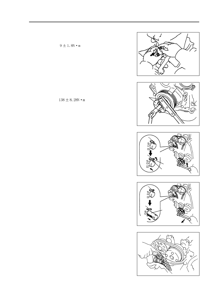
Engine mechanism - Timing chain assembly
(b) Coat engine oil on the chain tensioner, and then install
it.
Torque:
Note: when installing the chain temsioner, buckle
on the hook again if plunger has ejected.
33.
Install damping pulley.
(a) Align the key groove on the damping pulley with the
key on the crankshaft, and slide damping pulley in.
(b) Install damping pulley bolts with special tool.
Torque:
(c) Turn crankshaft counterclockwise to separate the hook
from lock pin on the plunger.
(d) Turn crankshaft clockwise, and check the chain ten-
sion rail is blocked by plunger.
Hint: if the plunger does not eject, press the chain ten-
sion rail toward chain tensioner with screwdriver
or fingers to separate the hook from lock pin and
make the plunger eject.
Special
tool
49
Pushing into
Separation
Hook
Pin
Turning
Plunger
Pushing
into
Turning