содержание .. 9 10 11 ..
Geely FC. Manual part - 10
Engine mechanism - Engine assembly
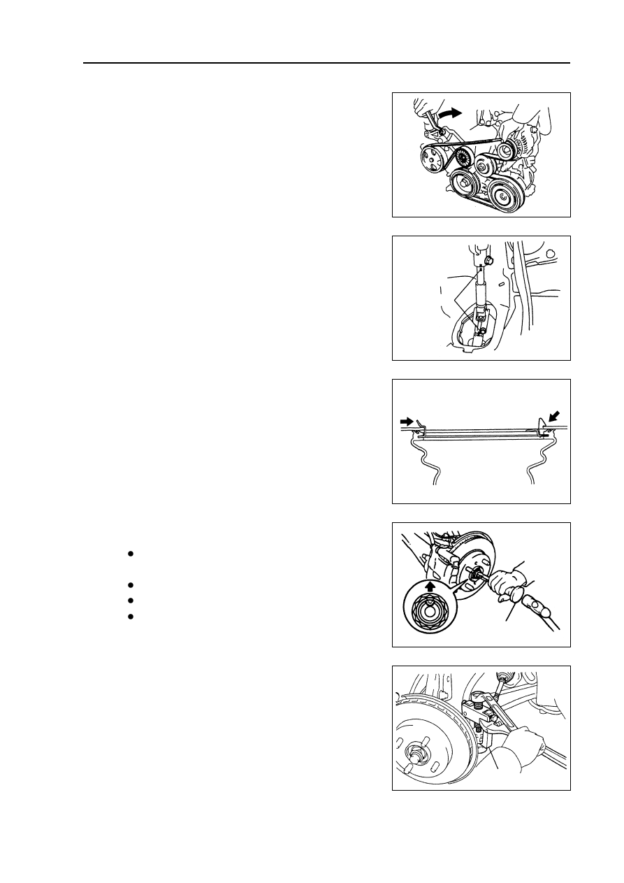
22.
Remove drive belt.
Drive belt tensioner could turn belt tensioner clockwise to
loosen it.
23.
Remove alternator mounting components [4G18-
3701100].
24.
Remove compressor assembly.
25.
Remove front chassis bracket.
26.
Remove front exhaust pipe assembly.
27.
Remove steering middle shaft assembly.
(a) Remove steering column seal hole cover.
(b) Make alignment mark on steering middle shaft.
(c) Remove 2 bolts and steering middle shaft.
(d) Remove steering column cover.
28.
Remove the nuts on left side of front shaft hub.
(a) Completely knock out the concave part of fixed nuts with
special tool and hammer.
Notes:
Completely knock out the concave part of fixed
nuts before removing the fixed nuts.
Do not damage thread of drive shaft.
Do not sharpen the sharp end of special tool.
Place the special tool in groove with its plane facing
upward.
(b) Remove fixed nuts with socket wrench (30mm).
Hint: perform the same steps at another side.
29.
Disassemble left side transversal lever assembly.
Disassemble transversal lever assembly from steering
knuckle with special tool.
Hint: perform the same steps at another side.
Alignment
mark
Special tool
Special tool
37
Sliding out
Lifting