Geely FC. Manual part - 24


  Главная      Geely     Geely FC. Workshop Manual year 2008


поиск по сайту            


содержание   ..   18  19  20  21  22  23  24  25  ..


Geely FC. Manual part - 24


Front suspension - Front shock absorber and helical spring

Handling

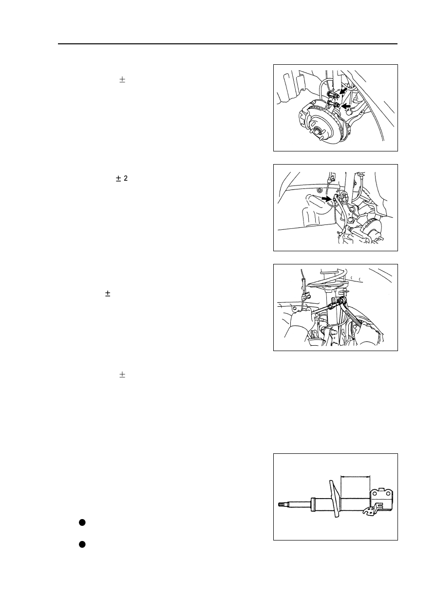
1. Handle front left absorber assembly.

(a) Completely pull out absorber piston rod.

(b) As shown in the diagram, drill a small hole on cylinder body

between two lines with electric drill to make inside gas flow

out

Notes:

Iron chip may fly out during drilling, please be care-

ful in operating.

The gas is colorless, odorless and nontoxic.

93

(c) Install 2 nuts to lower end of absorber.

Torque: 153

10 N.m

Hint: coat oil on thread of nuts.

(d) Install brake hose and ABS speed sensor wire harness

bracket with bolts.

Torque: 19

N.m

9. Install front left stabilizer link assembly [64000097].

Install stabilizer link with nuts.

Torque: 74

5 N.m

Hint: if ball joint rotates with nuts, please fix bolts with

hexagonal wrench (6mm).

10.

Install front wheels.

Torque: 103

10 N.m

11.

Check and adjust front wheel alignment

(see Page 87).

Front suspension - Lower left control arm assembly

Lower left control arm assembly

Replacement

Hint: the replacement procedures of right side are the

same as that of left side.

1. Remove front wheels.
2. Separate front left stabilizer link assembly

[64000097].

Remove nuts, and disassemble stabilizer link from shock

absorber.

Hint: if ball joint rotates with nuts, please fix bolts with

hex wrench (6mm).

3. Separate right side front stabilizer link assembly

[64000097].

4. Remove fixed nuts of front left drive shaft (see Page

123).

5. Separate front left wheel speed sensor assembly [67000020].

6. Separate front left brake wheel pump assembly (see Page 141).

7. Remove front left brake assembly [64000134] (see Page 142).

8. Separate left side transversal lever assembly.

9. Separate lower left control arm assembly [64000091].

Remove bolts and 2 nuts, and separate lower control arm

from lower end ball joint.

10.

Remove front left shaft hub assembly (see Page

123).

11.

Remove lower left control arm assembly

[64000091].

Remove 2 bolts, nuts and lower control arm.

12.

Temporarily  lock up lower left control arm as-

sembly [64000091].

Install lower control arm, and temporarily lock up 2 bolts

and nuts.

13.

Install front left shaft hub assembly (see Page

123).

14.

Install lower left control arm assembly [64000091].

Connect lower control arm with ball joint with 2 bolts and nuts.

Torque: 142

10 N.m

15.

Install left side transversal lever assembly.


(See Page 123)

16.

Install front left brake assembly.


[64000134] (See Page 141)

94

17.

Install front  left brake wheel pump bracket as-

sembly (see Page 141).

18.

Install fixed nuts of front left  drive shaft (see

Page 123).

19.

Install front left stabilizer link assembly

[64000097].

Install stabilizer link with nuts.

Torque: 74

5 N.m

Hint: if ball joint rotates with nuts, please fix bolts with

hex wrench (6mm).

20.

Install front right stabilizer link assembly

[64000097].

Hint: the installation procedures of right side are the

same as that of left side.

21.

Align suspension.

(a) Install front wheels and lay down vehicle from the lift.

Torque: 103

10 N.m

(b) Align suspension components by means of lifting ve-

hicle several times.

22.

Completely lock up lower left control arm assem-

bly [64000091].

Completely tighten 2 bolts and nuts.

Torque: 137

10 N.m

23.

Check and adjust front wheel alignment

(see Page 87).

24.

Check ABS sensor signal.

Front suspension - Lower left control arm assembly

95

Front suspension - Front stabilizer bar

Front stabilizer bar

Overhaul

1. Remove dust cap inside steering column (see Page 194).

2. Separate steering sliding shaft assembly (see Page 205)

3. Remove front wheels.

4. Remove right engine bottom shield.

5. Remove left engine bottom shield.

6. Remove  front left stabilizer link assembly

[64000097].

Remove 2 nuts and take down stabilizer link.

Hint: if ball joint rotates with nuts, please fix bolts with

hexagonal wrench (6mm).

7. Remove front right stabilizer link assembly

[64000097].

Hint: the removal procedures of right side are the same

as that of left side.

8. Check front left stabilizer link assembly.

(a) As shown in the diagram, before installing nuts, shake joint

bolts forward and backward 5 times.

(b) Shake nuts continuously with torque wrench at the speed

of one circle per 2 4 s, and then read out torque value at

the 5

th

 circle.

Rotating torque: 0.05~1.0 N.m

9. Separate left side transversal lever  assembly (see Page 113).

10.

Separate right side transversal lever assembly (see Page 113).

11.

Separate oil pipe assembly (see Page 205).

12.

Separate steering gear oil return pipe (see Page 205).

13.

Separate lower left control arm assembly [64000091] (see Page 94).

14.

Separate lower right control arm assembly [64000092] (see Page 94).

15.

Remove sub frame assembly [64000087] (see Page 205).

96


содержание   ..   18  19  20  21  22  23  24  25  ..