Freightliner FLA/FLB/FLC/FLD/FLL. Manual - part 22


  Index      Freightliner     Freightliner FLA/FLB/FLC/FLD/FLL - service manual 2009 year


Search            


Content   ..  20  21  22  23   ..


Freightliner FLA/FLB/FLC/FLD/FLL. Manual - part 22


5.

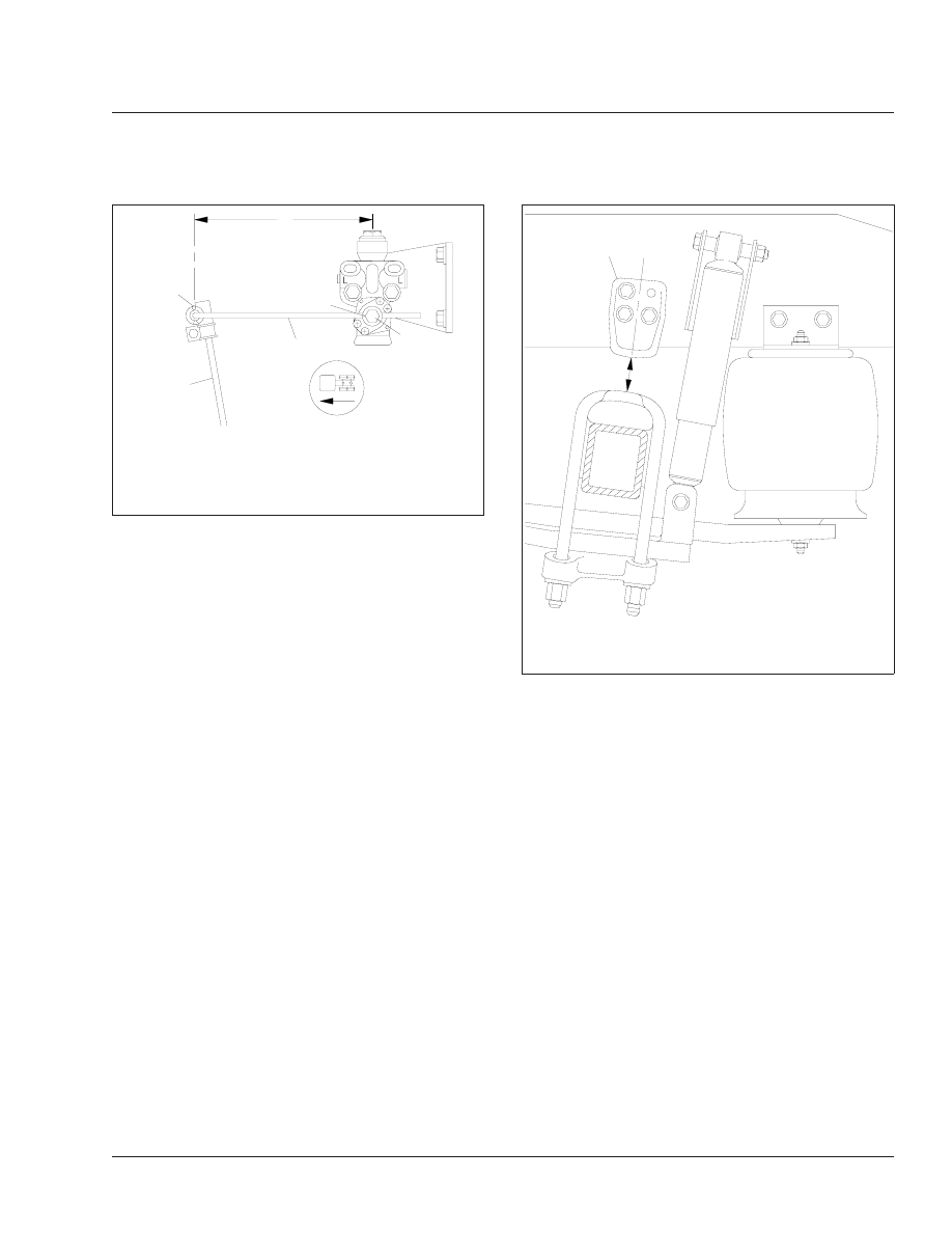
On single-drive rear axle configurations, measure
the distance from the bottom of the left axle stop
to the top of the U-bolt pad. On tandem (dual-
drive) rear axle configurations, measure the dis-
tance from the bottom of the forwardmost left
axle stop to the top of the axle U-bolt pad. See

Fig. 10

Ref. A. The correct distance for single

and dual-drive rear axles is between 2-3/8 inches
and 2-7/8 inches (60 to 73 mm).

6.

If the axle stop measurement is not correct, see
Group 32 of the

Heavy-Duty Trucks Service

Manual

for adjustment procedures.

7.

Without detaching the control rods, attempt to
move (by hand) each control-rod end up, down,
in, and out. If there is any movement, examine
the control rod for wear or damage. If a control
rod needs to be replaced, see Group 32 of the

Heavy-Duty Trucks Service Manual

for instruc-

tions.

8.

Inspect the rubber bushings for cracks or cuts.

9.

Check for any shifting of the barpin.

10. Inspect the weld seams between the control rod

tube and the shorter bushing tubes. If there are
cracks, replace the control rod. Do not weld the
control rod for any reason.

11. Raise the rear of the vehicle so the tires just

clear the ground and the suspension is fully ex-
tended. Place safety stands under the vehicle
frame.

12. Squeeze all air springs to check for complete

deflation. If any air springs remain partially or
fully inflated, see "Troubleshooting" in the appro-
priate section in Group 32 of the

Heavy-Duty

Trucks Service Manual

.

13. Inspect each air spring for wear at its connection

to its pedestal. Replace any worn air springs; for
instructions, see Group 32 of the

Heavy-Duty

Trucks Service Manual

.

14. Check the axle connection welds (beam-seat to

equalizing-beam and axle-adapter to axle) for
cracks. If welds are cracked, grind them out and
reweld the parts.

15. Move the axle up and down while checking for

signs of looseness due to worn parts at the front
pivot connections. Replace any worn parts by

3

4

2

A

05/15/95

f320410

1

5

A. Measure the length of the overtravel lever between

these two points.

1.

V-Shaped Mark

2.

Adjustment Locknut

3.

Overtravel Lever

4.

Cotter Pin

5.

Linkage Rod

Fig. 9, AirLiner Overtravel Lever and Linkage Rod

Measurement

08/16/96

f320453

A

1

A. Measure height here.
1.

Left Forwardmost Axle Stop

Fig. 10, AirLiner Axle Stop Measurement

Suspension

32

32/5

following the procedures in Group 32 of the

Heavy-Duty Trucks Service Manual

.

16. Inspect the shock absorbers for oil leaks and

worn rubber bushings. Replace the shock ab-
sorbers and/or rubber bushings if wear or dam-
age is noted. For instructions, see Group 32 of
the

Heavy-Duty Trucks Service Manual

.

17. Remove the safety stands and lower the rear of

the vehicle to the ground. Run the engine until
air pressure of at least 100 psi (689 kPa) is
maintained throughout the system.

18. Check that all air springs are inflated. If the air

springs do not inflate, see Group 32 of the

Heavy-Duty Trucks Service Manual

for possible

causes and corrections.

19. Apply the parking brakes and remove the

chocks.

Reyco 79KB and 179

Park the vehicle on level ground and chock the front
tires to prevent the vehicle from moving. Place the
transmission in neutral, and release the parking
brakes.

1.

Check that the torque rod clamps are directed
away from the spring to prevent possible interfer-
ence during operation. See

Fig. 11

for a Reyco

79KB, or

Fig. 12

for a Reyco 179.

2.

Check the fit of springs to hangers to ensure
good ride characteristics.

3.

Check for elongated holes in the suspension
components. See Group 32 of the

Heavy-Duty

Trucks Service Manual

for proper repair proce-

dures.

4.

Check bushing condition. Replace any bushing
that is worn, cracked, dry-rotted, or otherwise
damaged. See Group 32 of the

Heavy-Duty

Trucks Service Manual

for bushing removal and

installation instructions.

5.

Check tire condition. If abnormal wear is found,
check and replace all worn or damaged compo-
nents, and check suspension alignment. See
Group 32 of the

Heavy-Duty Trucks Service

Manual

for component removal and installation

procedures, and for suspension alignment in-
structions.

6.

Inspect all suspension fasteners for proper
torque values. See

Group 00

of this manual for

proper bolt torque specifications.

Chalmers Walking Beam
Suspension, 800 Series

Chock the front tires to prevent the vehicle from mov-
ing. Place the transmission in neutral, and release
the parking brakes before inspecting the Chalmers
rear suspension.

Power wash the Chalmers rear suspension, or clean
it with a hard-bristle brush before performing a visual
inspection.

1.

Visually inspect the rubber bushings for cracks or
other damage.

Try to move the torque rod ends using your
hands only, and check for any free-play. If free-
play is felt, replace the torque rod end bushing.
Do not use a pry bar to check for free-play. Use
of a pry bar may lead to premature bushing re-
placement.

2.

Lift the rear of the vehicle and support the frame
on jack stands to unload the suspension compo-
nents. The vehicle is lifted high enough when the
beam ends are off of the saddles. All jack stands
must be of sufficient strength and rigidity to
safely support the vehicle. Do not perform any
work on or around a vehicle that is supported
solely by a lifting device.

Visually inspect the walking beam for cracks or
other damage. If damage is found, replace the
walking beam.

Keep the vehicle supported by the jack stands
for the next operation.

3.

Manipulate the walking beam so that a microme-
ter, vernier, or dial caliper may be used to deter-
mine the wear area thickness on the bottom
face. See

Fig. 13

Measurements should be

taken a minimum of 1/2 inch from the beam
flange edges to eliminate any edge wear that
may have occurred. Subtract the wear area
thickness (

Fig. 13

Ref. B) from the thickness at

the non-wear area (

Fig. 13

Ref. A) to determine

the amount of wear.

If the beams show any wear greater than 0.062
inch (1.5 mm), a Chalmers wear plate must be
installed, or the walking beam must be replaced.

Suspension

32

32/6

4.

Rotate the restrictor cans 360 degrees and visu-
ally inspect the cans for cracks, severe corro-
sion, and distortion. If any of these conditions are
present, or the restrictor can is missing, replace
the restrictor can.

WARNING

Replace all cracked or missing restrictor cans.
Failure to do so could lead to loss of vehicle con-
trol, which could result in property damage, seri-

ous personal injury, or death. Vehicles with
cracked or missing restrictor cans may be driven

01/04/96

f320488

1

2

1

1.

Torque Rod Clamp

2.

Torque Rod

Fig. 11, Reyco 79KB Torque Rod Clamp Position

01/16/96

f320503

1

1

2

1.

Torque Rod Clamp

2.

Torque Rod

Fig. 12, Reyco 179 Torque Rod Clamp Position

09/27/95

f320432

1

A

B

A. Non-Wear Area

B. Wear Area

1.

Walking Beam

Fig. 13, Walking Beam End Wear Thickness

Suspension

32

32/7

slowly to the nearest workshop for restrictor can
replacement.

Hendrickson Walking Beam
Suspension, RS Series

1.

Inspect the frame hanger to frame attaching fas-
teners for the proper torque. See

Group 00

of

this manual for torque specifications.

WARNING

Be sure that fasteners are torqued correctly. Fas-
teners that do not provide a tightly clamped joint
between the frame and the hanger can cause pre-
mature fracture of the frame hanger, separation of
components, loss of vehicle control, and possible
personal injury or property damage.

2.

Visually inspect each frame hanger for any evi-
dence of cracks in the vertical mounting flange.
See

Fig. 14

.

3.

Visually inspect each frame hanger for evidence
of cracks in the horizontal mounting flange adja-
cent to the vertical drive pin area. See

Fig. 15

.

4.

Visually inspect each frame hanger for severe
rust on the horizontal mounting flange adjacent
to the vertical drive pin area. See

Fig. 16

.

5.

Inspect the load cushions for cuts and swelling.
See

Fig. 17

Cushions cut by the retaining lips of

the saddles or frame hangers indicate the cush-
ions may not be the correct hardness or configu-
ration for the vehicle operation.

6.

Inspect the lower side of the vertical drive bush-
ings for evidence of torn or shredded rubber.
Check that the concave washers are installed
with the lips pointing downward.

7.

Inspect the saddles and saddle cap fasteners for
wear. The allowable thrust washer wear in alumi-
num saddles is up to 3/16 inch (4.8 mm) into the
saddles as measured at the top of the thrust
washer diameter. Check that the locknuts are
torqued to specification to prevent wear of the
beam center bushings into the legs of the
saddles. See

Group 00

of this manual for torque

specifications.

09/15/95

f320419

1

2

1.

Frame Rail

2.

Crack in Inspection Area

Fig. 14, Hendrickson RS Series Vertical Mounting

Flange

09/15/95

f320420

1

1.

Crack in Inspection Area

Fig. 15, Hendrickson RS Series Horizontal Mounting

Flange

Suspension

32

32/8


Content   ..  20  21  22  23   ..